ProMatic - Hormann.fr
ProMatic - Hormann.fr
ProMatic - Hormann.fr
- No tags were found...

Create successful ePaper yourself
Turn your PDF publications into a flip-book with our unique Google optimized e-Paper software.
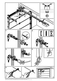
ENGLISHThe function of the mechanical release should be checkedevery month. The pull cord with knob may only be actuatedwhen the door is closed, otherwise in the case ofweak, broken or defective springs or due to a deficient /faulty counterbalance, there is a risk that the door couldclose extremely quickly.ATTENTIONNever hang bodily <strong>fr</strong>om the pull cord!All persons using the door system mustbe shown how to operate the garage dooropener properly and safely. Demonstrateand test the mechanical release as wellas the safety return. To do this, halt theclosing door by grasping it with bothhands. The door system should gentlycut-out and initiate the safety return.The same should happen during theopening cycle, i.e. the door systemgently cuts out and the door comes toa halt.3.6.1 Normal operationDuring normal operation the garage door operator worksexclusively on impulse sequence, whereby it makes no differencewhether the external button, a programmed handtransmitter button or the transparent button was pressed:1st Impulse: Operator causes door to move towardsan end-of-travel position.2nd Impulse: Operator causes door to stop.3rd Impulse: Operator causes door to travel in theopposite direction.4th Impulse: Operator causes door to stop.5th Impulse: Operator causes door to travel in thedirection of the end-of-travel positionselected when the first impulse wasgeneratedetc.The operator lighting comes on when the door movesand automatically goes out 3 minutes later on completionof the cycle.3.6.2 Operation following actuation of the mechanicalreleaseIf, for instance due to a power failure, the mechanicalrelease was actuated, the carriage must be re- engagedin the belt lock before normal operation can be resumed:1) Move the operator until the belt lock in the boom is wellaccessible for the carriage, and then stop the operator.2) Press the green button on the carriage (see figure 19).3) Move the door by hand until the carriage re- engagesin the belt lock.4) Carry out several uninterrupted travel cycles to checkwhether the door has fully reached its closed positionand whether it has also fully opened (the carriage comesto a halt shortly before the OPEN limit stop).NoteIf, after carrying out several uninterrupted travel cycles, thebehaviour/action does not correspond to that describedin stage 4, a new learn operation will be necessary (seesection 3.3.2).3.6.3 Signals <strong>fr</strong>om the operator lightingIf the mains plug is inserted without the transparentbutton (with operator cover removed the circuit boardbutton) being pressed, the operator lighting flashes two,three or four times.Flashing twiceindicates that no door data is stored or has been deleted(as in the ex factory state): programming can then becarried out immediately.Flashing three timesindicates that door data is stored but that the last doorposition is not sufficiently well known. The next travelcycle is therefore an OPEN reference cycle. This is thenfollowed by "normal" travel cycles.Flashing four timesindicates that not only is door data stored but also thatthe last door position is sufficiently well known, so that"normal" travel cycles taking into consideration the impulsesequence (OPEN-STOP-CLOSE-STOP etc.) canfollow (normal behaviour following successfully completedprogramming and a power failure). For safety reasons,whenever there is a power failure during a travelcycle, i.e. when the door is still in motion, the first impulsecommand always results in the door opening.NoteAn OPEN reference cycle can be enforced if, when themains plug is inserted, the external button (connectedat terminals 20 and 21a) is pressed. In this case, the operatorlighting flashes three times.Replacement lamp for operator lighting:24 V/10 W, socket: B(a)15s3.6.4 Error messages / diagnostic LED(light emitting diode, see figure 10.1)When operation does not go to plan, a diagnostic LED(visible through the transparent button even with theoperator cover in place), helps you to easily identify thepossible causes. In the programmed state this LED normallyglows constantly and goes out as long as an externallyconnected IMPULSE device is activated (seesection 3.5.2).NoteOn the basis of the behaviour explained above, a shortcircuitin the connecting lead of the external button or ashort-circuit in the button itself can be recognised even ifnormal operation of the garage door operator with the remotecontrol or the transparent button is otherwise possible.The operator is now ready to resume normaloperation.42 06.2004 TR10A014 RE