

RET_2015-01-02-03-04_Flipbook

You also want an ePaper? Increase the reach of your titles
YUMPU automatically turns print PDFs into web optimized ePapers that Google loves.
Grid voltage control with wind turbine inverters by using grid impedance estimation – Jonas De Kooning<br />
with a signal (active) or only observe the grid (passive), and if they measure transient<br />
effects or steady-state phenomena.<br />
The method which is the easiest in practical application and does not require additional<br />
measurements or components, is the (online active steady-state) non-characteristic<br />
current injection, [2]. In this method, a harmonic current is injected into the grid by the<br />
converter, a discrete Fourier transform (DFT) of both voltage and current is calculated<br />
and the estimated grid impedance results.<br />
4 SIMULATIONS<br />
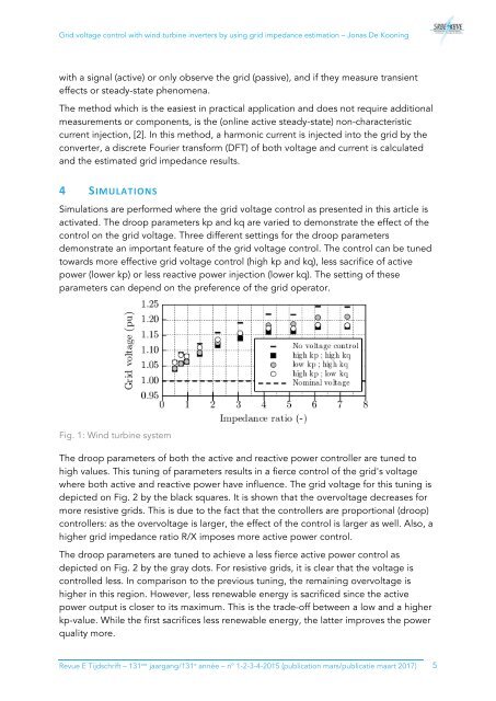
Simulations are performed where the grid voltage control as presented in this article is<br />
activated. The droop parameters kp and kq are varied to demonstrate the effect of the<br />
control on the grid voltage. Three different settings for the droop parameters<br />
demonstrate an important feature of the grid voltage control. The control can be tuned<br />
towards more effective grid voltage control (high kp and kq), less sacrifice of active<br />
power (lower kp) or less reactive power injection (lower kq). The setting of these<br />
parameters can depend on the preference of the grid operator.<br />
Fig. 1: Wind turbine system<br />
The droop parameters of both the active and reactive power controller are tuned to<br />
high values. This tuning of parameters results in a fierce control of the grid's voltage<br />
where both active and reactive power have influence. The grid voltage for this tuning is<br />
depicted on Fig. 2 by the black squares. It is shown that the overvoltage decreases for<br />
more resistive grids. This is due to the fact that the controllers are proportional (droop)<br />
controllers: as the overvoltage is larger, the effect of the control is larger as well. Also, a<br />
higher grid impedance ratio R/X imposes more active power control.<br />
The droop parameters are tuned to achieve a less fierce active power control as<br />
depicted on Fig. 2 by the gray dots. For resistive grids, it is clear that the voltage is<br />
controlled less. In comparison to the previous tuning, the remaining overvoltage is<br />
higher in this region. However, less renewable energy is sacrificed since the active<br />
power output is closer to its maximum. This is the trade-off between a low and a higher<br />
kp-value. While the first sacrifices less renewable energy, the latter improves the power<br />
quality more.<br />
Revue E Tijdschrift – 131 ste jaargang/131 e année – n° 1-2-3-4-<strong>2<strong>01</strong>5</strong> (publication mars/publicatie maart 2<strong>01</strong>7) 5