4-2019
Fachzeitschrift für Hochfrequenz- und Mikrowellentechnik
Fachzeitschrift für Hochfrequenz- und Mikrowellentechnik

Erfolgreiche ePaper selbst erstellen
Machen Sie aus Ihren PDF Publikationen ein blätterbares Flipbook mit unserer einzigartigen Google optimierten e-Paper Software.
5G Primer for MIMO/Phased Array Antennas<br />
Teil 4: 5G and MIMO Design With Circuit/Antenna Co-Simulation<br />
EM simulation software is commonly<br />
used to simulate antennas<br />
with multiple feeds, including<br />
phased arrays, stacked radiators<br />
with different polarizations,<br />
and single apertures with multiple<br />
feed points. These types<br />
of antennas are popular for<br />
communication systems where<br />
MIMO and polarization diversity<br />
antenna configurations are<br />
being rolled out.<br />
The beam of multiple-feed<br />
antennas is controlled by changing<br />
the phase and amplitude of<br />
the signals going into the various<br />
feeds. An accurate simulation of<br />
such a system must account for<br />
the interaction that occurs between<br />
the antenna elements and<br />
the driving feed network. The<br />
problem for simulation software<br />
is that the antenna and the<br />
driving feed network influence<br />
each other. The antenna’s pattern<br />
is changed by setting the input<br />
power and relative phasing at its<br />
various ports. At the same time,<br />
the input impedances at the ports<br />
change with the antenna pattern.<br />
Since input impedance affects<br />
the performance of the nonlinear<br />
driving circuit, the changing<br />
antenna pattern affects the overall<br />
system performance.<br />
Until now, engineers have been<br />
forced to simulate the coupled<br />
circuit/antenna effects manually<br />
using an iterative process.<br />
For example, first the antenna<br />
is driven with idealized sources<br />
with known phasing at the<br />
input ports. The impedance of<br />
the ports is then used as the load<br />
impedance for the driving circuit.<br />
The process is then iterated until<br />
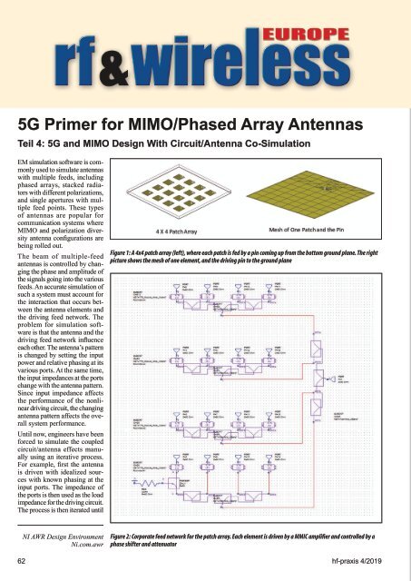
Figure 1: A 4x4 patch array (left), where each patch is fed by a pin coming up from the bottom ground plane. The right<br />
picture shows the mesh of one element, and the driving pin to the ground plane<br />
NI AWR Design Environment<br />
Ni.com.awr<br />
Figure 2: Corporate feed network for the patch array. Each element is driven by a MMIC amplifier and controlled by a<br />
phase shifter and attenuator<br />
62 hf-praxis 4/<strong>2019</strong>