4-2019
Fachzeitschrift für Hochfrequenz- und Mikrowellentechnik
Fachzeitschrift für Hochfrequenz- und Mikrowellentechnik

Sie wollen auch ein ePaper? Erhöhen Sie die Reichweite Ihrer Titel.
YUMPU macht aus Druck-PDFs automatisch weboptimierte ePaper, die Google liebt.
RF & Wireless<br />
can build up due to the loading<br />
at the antenna ports.<br />
Another often neglected but<br />
important point is that the PA<br />
driving the antenna requires a<br />
nonlinear circuit simulation. It<br />
is therefore important that the<br />
antenna’s S-parameters include a<br />
DC simulation point and values<br />
at the various harmonics used in<br />
the harmonic balance simulation.<br />
Otherwise it is possible to<br />
have unpredicted degradations<br />
in system performance due to<br />
poor matching at the harmonic<br />
frequencies or inaccurately specified<br />
DC biasing.<br />
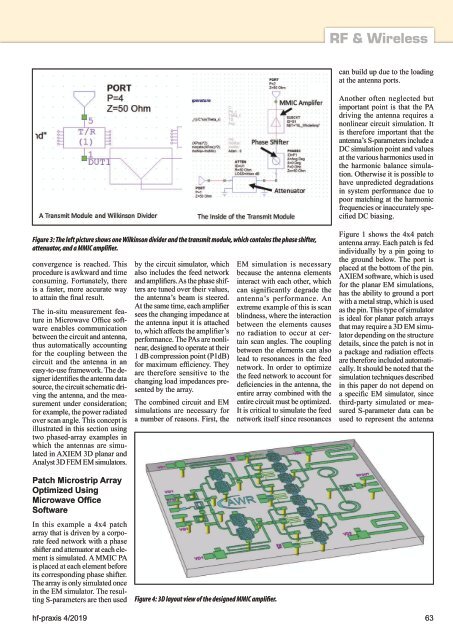
Figure 3: The left picture shows one Wilkinson divider and the transmit module, which contains the phase shifter,<br />
attenuator, and a MMIC amplifier.<br />
convergence is reached. This<br />
procedure is awkward and time<br />
consuming. Fortunately, there<br />
is a faster, more accurate way<br />
to attain the final result.<br />
The in-situ measurement feature<br />
in Microwave Office software<br />
enables communication<br />
between the circuit and antenna,<br />
thus automatically accounting<br />
for the coupling between the<br />
circuit and the antenna in an<br />
easy-to-use framework. The designer<br />
identifies the antenna data<br />
source, the circuit schematic driving<br />
the antenna, and the measurement<br />
under consideration;<br />
for example, the power radiated<br />
over scan angle. This concept is<br />
illustrated in this section using<br />
two phased-array examples in<br />
which the antennas are simulated<br />
in AXIEM 3D planar and<br />
Analyst 3D FEM EM simulators.<br />
by the circuit simulator, which<br />
also includes the feed network<br />
and amplifiers. As the phase shifters<br />
are tuned over their values,<br />
the antenna’s beam is steered.<br />
At the same time, each amplifier<br />
sees the changing impedance at<br />
the antenna input it is attached<br />
to, which affects the amplifier’s<br />
performance. The PAs are nonlinear,<br />
designed to operate at their<br />
1 dB compression point (P1dB)<br />
for maximum efficiency. They<br />
are therefore sensitive to the<br />
changing load impedances presented<br />
by the array.<br />
The combined circuit and EM<br />
simulations are necessary for<br />
a number of reasons. First, the<br />
EM simulation is necessary<br />
because the antenna elements<br />
interact with each other, which<br />
can significantly degrade the<br />
antenna’s performance. An<br />
extreme example of this is scan<br />
blindness, where the interaction<br />
between the elements causes<br />
no radiation to occur at certain<br />
scan angles. The coupling<br />
between the elements can also<br />
lead to resonances in the feed<br />
network. In order to optimize<br />
the feed network to account for<br />
deficiencies in the antenna, the<br />
entire array combined with the<br />
entire circuit must be optimized.<br />
It is critical to simulate the feed<br />
network itself since resonances<br />
Figure 1 shows the 4x4 patch<br />
antenna array. Each patch is fed<br />
individually by a pin going to<br />
the ground below. The port is<br />
placed at the bottom of the pin.<br />
AXIEM software, which is used<br />
for the planar EM simulations,<br />
has the ability to ground a port<br />
with a metal strap, which is used<br />
as the pin. This type of simulator<br />
is ideal for planar patch arrays<br />
that may require a 3D EM simulator<br />
depending on the structure<br />
details, since the patch is not in<br />
a package and radiation effects<br />
are therefore included automatically.<br />
It should be noted that the<br />
simulation techniques described<br />
in this paper do not depend on<br />
a specific EM simulator, since<br />
third-party simulated or measured<br />
S-parameter data can be<br />
used to represent the antenna<br />
Patch Microstrip Array<br />
Optimized Using<br />
Microwave Office<br />
Software<br />
In this example a 4x4 patch<br />
array that is driven by a corporate<br />
feed network with a phase<br />
shifter and attenuator at each element<br />
is simulated. A MMIC PA<br />
is placed at each element before<br />
its corresponding phase shifter.<br />
The array is only simulated once<br />
in the EM simulator. The resulting<br />
S-parameters are then used<br />
Figure 4: 3D layout view of the designed MMIC amplifier.<br />
hf-praxis 4/<strong>2019</strong> 63