4-2019
Fachzeitschrift für Hochfrequenz- und Mikrowellentechnik
Fachzeitschrift für Hochfrequenz- und Mikrowellentechnik

Sie wollen auch ein ePaper? Erhöhen Sie die Reichweite Ihrer Titel.
YUMPU macht aus Druck-PDFs automatisch weboptimierte ePaper, die Google liebt.
RF & Wireless<br />
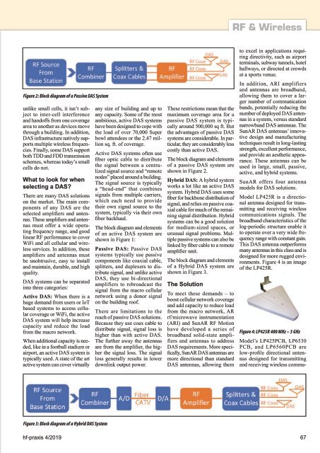
Figure 2: Block diagram of a Passive DAS System<br />
unlike small cells, it isn’t subject<br />
to inter-cell interference<br />
and handoffs from one coverage<br />
area to another as devices move<br />
through a building. In addition,<br />
DAS infrastructure natively supports<br />
multiple wireless frequencies.<br />
Finally, some DAS support<br />
both TDD and FDD transmission<br />
schemes, whereas today’s small<br />
cells do not.<br />
What to look for when<br />
selecting a DAS?<br />
There are many DAS solutions<br />
on the market. The main components<br />
of any DAS are the<br />
selected amplifiers and antennas.<br />
These amplifiers and antennas<br />
must offer a wide operating<br />
frequency range, and good<br />
linear RF performance to cover<br />
WiFi and all cellular and wireless<br />
services. In addition, these<br />
amplifiers and antennas must<br />
be unobtrusive, easy to install<br />
and maintain, durable, and high<br />
quality.<br />
DAS systems can be separated<br />
into three categories:<br />
Active DAS: When there is a<br />
huge demand from users or IoT<br />
based systems to access cellular<br />
coverage or WiFi, the active<br />
DAS system will help increase<br />
capacity and reduce the load<br />
from the macro network.<br />
When additional capacity is needed,<br />
like in a football stadium or<br />
airport, an active DAS system is<br />
typically used. A state of the art<br />
active system can cover virtually<br />
any size of building and up to<br />
any capacity. Some of the most<br />
ambitious, active DAS systems<br />
have been designed to cope with<br />
the load of over 70,000 Super<br />
bowl attendees or the 2.47 million<br />
sq. ft. of coverage.<br />
Active DAS systems often use<br />
fiber optic cable to distribute<br />
the signal between a centralized<br />
signal source and “remote<br />
nodes” placed around a building.<br />
The signal source is typically<br />
a “head-end” that combines<br />
signals from multiple carriers,<br />
which each need to provide<br />
their own signal source to the<br />
system, typically via their own<br />
fiber backhaul.<br />
The block diagram and elements<br />
of an active DAS system are<br />
shown in Figure 1:<br />
Passive DAS: Passive DAS<br />
systems typically use passive<br />
components like coaxial cable,<br />
splitters, and duplexers to distribute<br />
signal, and unlike active<br />
DAS, they use bi-directional<br />
amplifiers to rebroadcast the<br />
signal from the macro cellular<br />
network using a donor signal<br />
on the building roof.<br />
There are limitations to the<br />
reach of passive DAS solutions.<br />
Because they use coax cable to<br />
distribute signal, signal loss is<br />
higher than with active DAS.<br />
The further away the antennas<br />
are from the amplifier, the higher<br />
the signal loss. The signal<br />
loss generally results in lower<br />
downlink output power.<br />
These restrictions mean that the<br />
maximum coverage area for a<br />
passive DAS system is typically<br />
around 500,000 sq ft. But<br />
the advantages of passive DAS<br />
systems are considerable. In particular,<br />
they are considerably less<br />
costly than active DAS.<br />
The block diagram and elements<br />
of a passive DAS system are<br />
shown in Figure 2.<br />
Hybrid DAS: A hybrid system<br />
works a lot like an active DAS<br />
system. Hybrid DAS uses some<br />
fiber for backbone distribution of<br />
signal, and relies on passive coaxial<br />
cable for much of the remaining<br />
signal distribution. Hybrid<br />
systems can be a good solution<br />
for medium-sized spaces, or<br />
unusual signal problems. Multiple<br />
passive systems can also be<br />
linked by fiber cable to a remote<br />
amplifier unit.<br />
The block diagram and elements<br />
of a Hybrid DAS system are<br />
shown in Figure 3.<br />
The Solution<br />
To meet these demands – to<br />
boost cellular network coverage<br />
and add capacity to reduce load<br />
from the macro network, AR<br />
rf/microwave instrumentation<br />
(ARI) and SunAR RF Motion<br />
have developed a series of<br />
broadband solid-state amplifiers<br />
and antennas to address<br />
DAS requirements. More specifically,<br />
SunAR DAS antennas are<br />
more directional than standard<br />
DAS antennas, allowing them<br />
to excel in applications requiring<br />
directivity, such as airport<br />
terminals, subway tunnels, hotel<br />
hallways, or directed at crowds<br />
at a sports venue.<br />
In addition, ARI amplifiers<br />
and antennas are broadband,<br />
allowing them to cover a larger<br />
number of communication<br />
bands, potentially reducing the<br />
number of deployed DAS antennas<br />
in a system, versus standard<br />
narrowband DAS antennas. The<br />
SunAR DAS antennas’ innovative<br />
design and manufacturing<br />
techniques result in long-lasting<br />
strength, excellent performance,<br />
and provide an aesthetic appearance.<br />
These antennas can be<br />
used in large, small, passive,<br />
active, and hybrid systems.<br />
SunAR offers four antenna<br />
models for DAS solutions.<br />
Model LP425R is a directional<br />
antenna designed for transmitting<br />
and receiving wireless<br />
communications signals. The<br />
broadband characteristics of the<br />
log-periodic structure enable it<br />
to operate over a very wide frequency<br />
range with constant gain.<br />
This DAS antenna outperforms<br />
many antennas in this class and is<br />
designed for more rugged environments.<br />
Figure 4 is an image<br />
of the LP425R.<br />
Figure 4: LP425R 400 MHz – 3 GHz<br />
Model’s LP425PCB, LP 6530<br />
PCB, and LP6560PCB are<br />
low-profile directional antennas<br />
designed for transmitting<br />
and receiving wireless commu-<br />
Figure 3: Block diagram of a Hybrid DAS System<br />
hf-praxis 4/<strong>2019</strong> 67