

Introduction to Microcontrollers Lab Manual - Microchip
Introduction to Microcontrollers Lab Manual - Microchip
Introduction to Microcontrollers Lab Manual - Microchip

Create successful ePaper yourself
Turn your PDF publications into a flip-book with our unique Google optimized e-Paper software.
LABS<br />
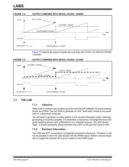
FIGURE 7-4: OUTPUT COMPARE WITH INITIAL OCxRS = 0x0000<br />
Figure 7-5 depicts the output compare pin over time with OCxR = 0x1000 and OCxRS<br />
= 0x5000.<br />
FIGURE 7-5: OUTPUT COMPARE WITH INITIAL OCxRS = 0x1000<br />
7.3 THE LAB<br />
7.3.1 Objective<br />
Write code <strong>to</strong> configure and enable one of the nine PIC24FJ256GB110 output compare<br />
blocks as a PWM. Use the PWM <strong>to</strong> generate an LED “heart beat” similar <strong>to</strong> the power<br />
LED on a Macin<strong>to</strong>sh computer.<br />
You will need <strong>to</strong> generate a similar pattern <strong>to</strong> the sinusoid illustrated earlier. Although<br />
generating a sinusoid is possible, it is somewhat unnecessary. A triangle like wave with<br />
some tweaking should work sufficiently for our intended purpose. The LED should<br />
“beat”. It should repeatedly slowly transition from OFF <strong>to</strong> ON and then back <strong>to</strong> OFF.<br />
7.3.2 Pertinent Information<br />
The LEDs are NOT connected <strong>to</strong> remappable peripheral output pins. Therefore, it will<br />
not be possible <strong>to</strong> drive the LED directly with the PWM output. Rather it will be necessary<br />
<strong>to</strong> <strong>to</strong>ggle the desired LED port pin based on the PWM output.<br />
DS51963A-page 54 2011 <strong>Microchip</strong> Technology Inc.


