THE ROLE OF THE
THE ROLE OF THE
THE ROLE OF THE

You also want an ePaper? Increase the reach of your titles
YUMPU automatically turns print PDFs into web optimized ePapers that Google loves.
Manufacturing and Process Technology 73<br />
Mold<br />
Heater<br />
Polymer sheet<br />
Mold<br />
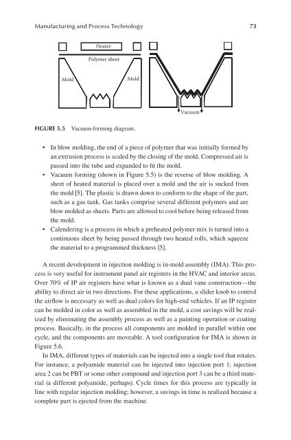
FIgure 5.5 Vacuum-forming diagram.<br />
Vacuum<br />
• In blow molding, the end of a piece of polymer that was initially formed by<br />
an extrusion process is scaled by the closing of the mold. Compressed air is<br />
passed into the tube and expanded to fit the mold.<br />
• Vacuum forming (shown in Figure 5.5) is the reverse of blow molding. A<br />
sheet of heated material is placed over a mold and the air is sucked from<br />
the mold [5]. The plastic is drawn down to conform to the shape of the part,<br />
such as a gas tank. Gas tanks comprise several different polymers and are<br />
blow molded as sheets. Parts are allowed to cool before being released from<br />
the mold.<br />
• Calendering is a process in which a preheated polymer mix is turned into a<br />
continuous sheet by being passed through two heated rolls, which squeeze<br />
the material to a programmed thickness [5].<br />
A recent development in injection molding is in-mold assembly (IMA). This process<br />
is very useful for instrument panel air registers in the HVAC and interior areas.<br />
Over 70% of IP air registers have what is known as a dual vane construction—the<br />
ability to direct air in two directions. For these applications, a slider knob to control<br />
the airflow is necessary as well as dual colors for high-end vehicles. If an IP register<br />
can be molded in color as well as assembled in the mold, a cost savings will be realized<br />
by eliminating the assembly process as well as a painting operation or coating<br />
process. Basically, in the process all components are molded in parallel within one<br />
cycle, and the components are moveable. A tool configuration for IMA is shown in<br />
Figure 5.6.<br />
In IMA, different types of materials can be injected into a single tool that rotates.<br />
For instance, a polyamide material can be injected into injection port 1; injection<br />
area 2 can be PBT or some other compound and injection port 3 can be a third material<br />
(a different polyamide, perhaps). Cycle times for this process are typically in<br />
line with regular injection molding; however, a savings in time is realized because a<br />
complete part is ejected from the machine.