

Download - heidenhain - DR. JOHANNES HEIDENHAIN GmbH
Download - heidenhain - DR. JOHANNES HEIDENHAIN GmbH
Download - heidenhain - DR. JOHANNES HEIDENHAIN GmbH

You also want an ePaper? Increase the reach of your titles
YUMPU automatically turns print PDFs into web optimized ePapers that Google loves.
5 Pin Layouts<br />
5.1 Pin Layout of PWM 20<br />
5.2 Pin Layout of the IK 215<br />
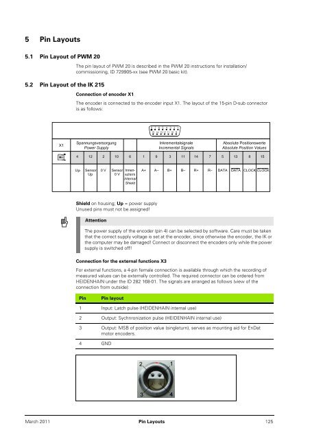
X1<br />
The pin layout of PWM 20 is described in the PWM 20 instructions for installation/<br />
commissioning, ID 729905-xx (see PWM 20 basic kit).<br />
Connection of encoder X1<br />
The encoder is connected to the encoder input X1. The layout of the 15-pin D-sub connector<br />
is as follows:<br />
Spannungsversorgung<br />
Power Supply<br />
0 V Sensor Innen-<br />
0 V schirm<br />
Internal<br />
Shield<br />
Shield on housing; Up = power supply<br />
Unused pins must not be assigned!<br />
8 7 6 5 4 3 2 1<br />
15 14 13 12 11 10 9<br />
Connection for the external functions X3<br />
Inkrementalsignale<br />
Incremental Signals<br />
Absolute Positionswerte<br />
Absolute Position Values<br />
4 12 2 10 6 1 9 3 11 14 7 5 13 8 15<br />
U P Sensor<br />
U P<br />
Attention<br />
A+ A– B+ B– R+ R– DATA DATA CLOCK CLOCK<br />
The power supply of the encoder (pin 4) can be selected by software. Care must be taken<br />
that the correct supply voltage is set at the encoder, since otherwise the encoder, the IK or<br />
the computer may be damaged! Connect or disconnect the encoders only while the power<br />
supply is switched off!<br />
For external functions, a 4-pin female connection is available through which the recording of<br />
measured values can be externally controlled. The required connector can be ordered from<br />
<strong>HEIDENHAIN</strong> under the ID 282 168-01. The signals are arranged as follows (view of the<br />
connection from outside):<br />
Pin Pin layout<br />
1 Input: Latch pulse (<strong>HEIDENHAIN</strong> internal use)<br />
2 Output: Sychnronization pulse (<strong>HEIDENHAIN</strong> internal use)<br />
3 Output: MSB of position value (singleturn), serves as mounting aid for EnDat<br />
motor encoders.<br />
4 GND<br />
March 2011 Pin Layouts 125


