

appendix 1 - Victor Technologies
appendix 1 - Victor Technologies
appendix 1 - Victor Technologies

Create successful ePaper yourself
Turn your PDF publications into a flip-book with our unique Google optimized e-Paper software.
The Logic PC Board controls the timing and sequencing of<br />
the system. It monitors the pressure, temperature, and<br />
flow interlocks and controls the gas flow in run and set<br />
modes by turning on the plasma and secondary solenoids.<br />
The Logic PC Board also controls the power on the voltage<br />
selection and prepurge functions.<br />
After the ON/OFF switch is closed on the front panel, the<br />
AC Indicator blinks and the GAS Indicator is on steady.<br />
The AC Indicator blinks for approximately 8 seconds then<br />
at that time it becomes steady and the inrush relay closes.<br />
The GAS Indicator stays on for approximately 20 seconds<br />
(prepurge function) then goes off and the gas stops flowing.<br />
When the torch switch is pressed, D26 "start" Indicator<br />
comes on, gas will flow for approximately 2 seconds before<br />
DC is established (indicated on the front panel). During<br />
this time D25 CD Enable will come on and sends a logic<br />
signal to the CD Board which fires the spark gap and initiates<br />
the torch to pilot. D25 should go out immediately if<br />
the pilot starts immediately.<br />
When the torch is close to the workpiece, the cutting arc<br />
"transfers" to the work. Also, if the tip touches the workpiece,<br />
the current is automatically folded back to approximately<br />
35 amps to save the tip from being blown out.<br />
The resulting current is sensed by the Current Sense PC<br />
Board, resulting in the demand level changing from pilot<br />
current to whatever the main current control is set at. During<br />
the "transfer" the CSR Indicator (D65) comes on and<br />
the transfer enable signal goes low allowing the bottom<br />
gate drive and FET modules to come up and start running.<br />
Also at this time, D5 (located on the Pilot Output PC Board)<br />
shuts off and at this time the main cutting arc is initiated. If<br />
the torch is removed from the workpiece, the pilot arc will<br />
automatically restart if the torch switch is still pressed.<br />
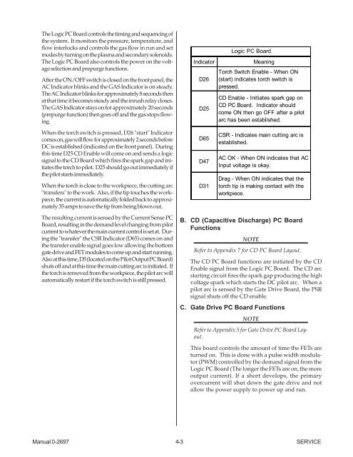
Indicator Meaning<br />
Manual 0-2697 4-3 SERVICE<br />
D26<br />
D25<br />
D65<br />
D47<br />
D31<br />
Logic PC Board<br />
Torch Switch Enable - When ON<br />
(start) indicates torch switch is<br />
pressed.<br />
CD Enable - Initiates spark gap on<br />
CD PC Board. Indicator should<br />
come ON then go OFF after a pilot<br />
arc has been established.<br />
CSR - Indicates main cutting arc is<br />
established.<br />
AC OK - When ON indicates that AC<br />
Input voltage is okay.<br />
Drag - When ON indicates that the<br />
torch tip is making contact with the<br />
workpiece.<br />
B. CD (Capacitive Discharge) PC Board<br />
Functions<br />
NOTE<br />
Refer to Appendix 7 for CD PC Board Layout.<br />
The CD PC Board functions are initiated by the CD<br />
Enable signal from the Logic PC Board. The CD arc<br />
starting circuit fires the spark gap producing the high<br />
voltage spark which starts the DC pilot arc. When a<br />
pilot arc is sensed by the Gate Drive Board, the PSR<br />
signal shuts off the CD enable.<br />
C. Gate Drive PC Board Functions<br />
NOTE<br />
Refer to Appendix 5 for Gate Drive PC Board Layout.<br />
This board controls the amount of time the FETs are<br />
turned on. This is done with a pulse width modulator<br />
(PWM) controlled by the demand signal from the<br />
Logic PC Board (The longer the FETs are on, the more<br />
output current). If a short develops, the primary<br />
overcurrent will shut down the gate drive and not<br />
allow the power supply to power up and run.


