

appendix 1 - Victor Technologies
appendix 1 - Victor Technologies
appendix 1 - Victor Technologies

Create successful ePaper yourself
Turn your PDF publications into a flip-book with our unique Google optimized e-Paper software.
I. FET/Heatsink Assembly Replacement<br />
CAUTION<br />
The FET/Heatsink Assemblies are matched and<br />
balanced during production and must be replaced<br />
in pairs.<br />
NOTE<br />
The four FET/Heatsink Assemblies are identical<br />
and are removed in the same manner.<br />
1. Remove the Left Side Panel per Section 5.04-A.<br />
2. Remove the Ribbon Cable plugs at J6 on the FET/<br />
Heatsink Assembly. To remove the cable, push<br />
down on the locking tab and pull the cable plug<br />
out of the connector.<br />
3. Disconnect all the wire lug connections to the FET/<br />
Heatsink Assembly.<br />
Connection Description<br />
E14 Main Transformer (Primary)<br />
E15 Main Transformer (Primary)<br />
E16 Main Transformer (Secondary)<br />
E17 (-) Output<br />
E18 (+) Output<br />
E19 Main Transformer (Secondary)<br />
4. Disconnect the wiring from wire lug connections<br />
on the Capacitor PC Board at E25 (+) and E26 (-)<br />
terminals.<br />
5. Remove the two screws securing the Heatsink<br />
Mounting Bracket to the chassis.<br />
6. To remove the Mounting Bracket lift up on the<br />
top FET/Heatsink Assembly and push down on<br />
the bottom FET/Heatsink Assembly in the middle<br />
where the two FET/Heatsink Assemblies come<br />
together.<br />
7. Slide the FET/Heatsink Assembly out and up to<br />
remove the FET/Heatsink Assembly from the<br />
unit.<br />
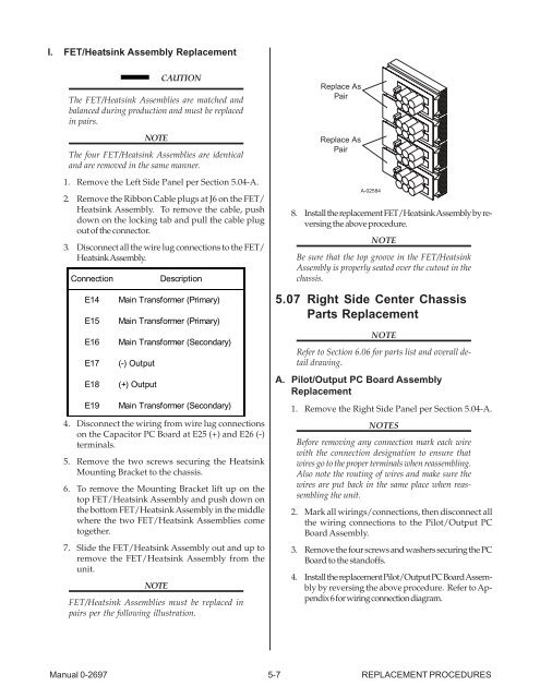
NOTE<br />
FET/Heatsink Assemblies must be replaced in<br />
pairs per the following illustration.<br />
Replace As<br />
Pair<br />
Replace As<br />
Pair<br />
Manual 0-2697 5-7 REPLACEMENT PROCEDURES<br />
A-02584<br />
8. Install the replacement FET/Heatsink Assembly by reversing<br />
the above procedure.<br />
NOTE<br />
Be sure that the top groove in the FET/Heatsink<br />
Assembly is properly seated over the cutout in the<br />
chassis.<br />
5.07 Right Side Center Chassis<br />
Parts Replacement<br />
NOTE<br />
Refer to Section 6.06 for parts list and overall detail<br />
drawing.<br />
A. Pilot/Output PC Board Assembly<br />
Replacement<br />
1. Remove the Right Side Panel per Section 5.04-A.<br />
NOTES<br />
Before removing any connection mark each wire<br />
with the connection designation to ensure that<br />
wires go to the proper terminals when reassembling.<br />
Also note the routing of wires and make sure the<br />
wires are put back in the same place when reassembling<br />
the unit.<br />
2. Mark all wirings/connections, then disconnect all<br />
the wiring connections to the Pilot/Output PC<br />
Board Assembly.<br />
3. Remove the four screws and washers securing the PC<br />
Board to the standoffs.<br />
4. Install the replacement Pilot/Output PC Board Assembly<br />
by reversing the above procedure. Refer to Appendix<br />
6 for wiring connection diagram.


