

appendix 1 - Victor Technologies
appendix 1 - Victor Technologies
appendix 1 - Victor Technologies

You also want an ePaper? Increase the reach of your titles
YUMPU automatically turns print PDFs into web optimized ePapers that Google loves.
9. Slide reservoir panel up and out of the 'T' slots on the<br />
center chassis and move panel to provide access to<br />
main transformers.<br />
10. Carefully remove all wire connections to the FET PCB<br />
Assembly noting the location of each per the following<br />
chart:<br />
Cable #<br />
FET PCB<br />
Connection<br />
14A E14<br />
15A E15<br />
16A E16<br />
19A E19<br />
14B E14<br />
15B E15<br />
16B E16<br />
19B E19<br />
NOTES<br />
Make sure white #19 wires are looped around and<br />
connected from the right side.<br />
Transformer leads are marked 'A' & 'B'. Group<br />
'A' is wired to the top heatsink and group 'B' is<br />
wired to the bottom heatsink. Wires are placed belly<br />
up."<br />
11. Note orientation of Main Transformer Assembly,<br />
then remove four lock nuts securing Transformer<br />
to the center chassis.<br />
12. Install the replacement Transformer Assembly by reversing<br />
the above procedure, keeping in mind the following:<br />
Reservoir Panel must seat in corresponding center<br />
chassis slots.<br />
The four screws securing the output inductor<br />
mounting plate to the center chassis should have a<br />
maximum of 2 to 5 threads protruding through the<br />
left side of the chassis.<br />
L. Pilot Panel Fan (M1 - M4) Replacement<br />
NOTE<br />
There are four Fans mounted to the Pilot Fan<br />
Panel. Replacement instructions are the same for<br />
all Fans.<br />
1. Remove Front Panel per Section 5.04-E.<br />
2. Remove the two screws securing the Fan to the two<br />
tabs on the Pilot Fan Panel.<br />
3. Turn the fan sideways and pull gently out of unit to<br />
where the wires can be disconnected.<br />
4. Carefully note wiring connections, then disconnect<br />
wires.<br />
5. Install replacement Fan(s) by reversing the above<br />
steps, noting the following:<br />
a. Piggyback tabs face outside.<br />
b. Label faces inside unit.<br />
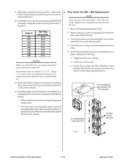
c. Orient Fan so that Air Flow/Rotation Label<br />
molded into the Fan Housing is positioned as<br />
shown in the following illustration.<br />
ROTATION<br />
Air Flow/Rotation<br />
Label Direction<br />
REPLACEMENT PROCEDURES 5-12 Manual 0-2697<br />
A-02290<br />
AIR FLOW<br />
Air Flow/Rotation<br />
Label Molded Into<br />
Fan Housing<br />
Air Flow<br />
Arrow<br />
Direction


