

appendix 1 - Victor Technologies
appendix 1 - Victor Technologies
appendix 1 - Victor Technologies

You also want an ePaper? Increase the reach of your titles
YUMPU automatically turns print PDFs into web optimized ePapers that Google loves.
7. Remove rear panel from unit by completing the following:<br />
a. Remove the two screws on near bottom of rear panel<br />
securing the panel to the base of the unit.<br />
b. Remove the two nuts and washers on the inside of<br />
rear panel connecting the panel to the center chassis.<br />
c. Remove screw located in the center of the rear panel<br />
securing the rear panel to the frame.<br />
d. Carefully lift the rear panel up, over the reservoir,<br />
and away from the power supply.<br />
8. To install replacement rear panel, reverse the above<br />
procedure.<br />
C. Pressure Switch (PS1) Replacement<br />
1. Remove the Right Side Panel per Section 5.04-A.<br />
2. Disconnect the two wires connected to the Pressure<br />
Switch Assembly (see Figure below).<br />
3. Remove the Pressure Switch Assembly from the T-fitting.<br />
4. Install the replacement Pressure Switch Assembly by<br />
reversing the above procedure, keeping in mind the<br />
following:<br />
Apply pipe thread sealant to the fitting before reassembling.<br />
D. Solenoid Valve (SOL1 & SOL2)<br />
Replacement<br />
NOTE<br />
There are two Solenoid Valve Assemblies in this<br />
unit; one for plasma gas and one for secondary gas<br />
(as labeled on rear panel). The Solenoid Assembly<br />
for secondary gas has a Pressure Switch which must<br />
be removed before the Solenoid can be removed. Following<br />
the instructions as they pertain to the Solenoid<br />
Valve being replaced.<br />
1. Remove the Right Side Panel per Section 5.04-A.<br />
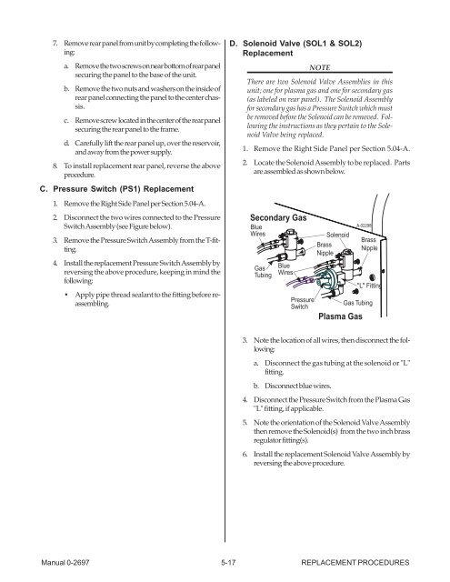
2. Locate the Solenoid Assembly to be replaced. Parts<br />
are assembled as shown below.<br />
Secondary Gas<br />
Blue<br />
Wires Solenoid<br />
Brass<br />
Nipple<br />
Gas<br />
Tubing<br />
Pressure<br />
Switch<br />
Gas Tubing<br />
Plasma Gas<br />
Manual 0-2697 5-17 REPLACEMENT PROCEDURES<br />
Blue<br />
Wires<br />
A-02298<br />
Brass<br />
Nipple<br />
"L" Fitting<br />
3. Note the location of all wires, then disconnect the following:<br />
a. Disconnect the gas tubing at the solenoid or "L"<br />
fitting.<br />
b. Disconnect blue wires.<br />
4. Disconnect the Pressure Switch from the Plasma Gas<br />
"L" fitting, if applicable.<br />
5. Note the orientation of the Solenoid Valve Assembly<br />
then remove the Solenoid(s) from the two inch brass<br />
regulator fitting(s).<br />
6. Install the replacement Solenoid Valve Assembly by<br />
reversing the above procedure.


