Hi-Res PDF - CRCnetBASE
Hi-Res PDF - CRCnetBASE
Hi-Res PDF - CRCnetBASE

Create successful ePaper yourself
Turn your PDF publications into a flip-book with our unique Google optimized e-Paper software.
248<br />
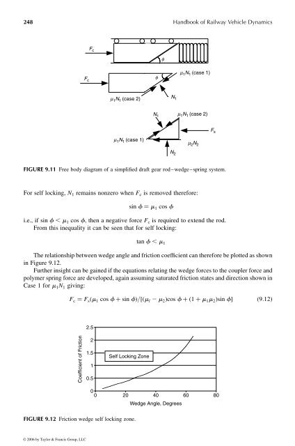
For self locking, N 1 remains nonzero when F c is removed therefore:<br />
sin f ¼ m 1 cos f<br />
i.e., if sin f , m 1 cos f ; then anegative force F c is required to extend the rod.<br />
From this inequality it can be seen that for self locking:<br />
tan f , m 1<br />
Therelationship betweenwedge angleand friction coefficient can therefore be plottedasshown<br />
in Figure 9.12.<br />
Further insight can be gained if the equations relating the wedge forces to the coupler force and<br />
polymer spring force are developed, again assuming saturated friction states and direction shown in<br />
Case 1for m 1 N 1 giving:<br />
F c ¼ F s ð m 1 cos f þ sin f Þ = ½ðm l 2 m 2 Þ cos f þð1 þ m 1 m 2 Þ sin f � ð9 : 12Þ<br />
Coefficient of Friction<br />
2.5<br />
2<br />
1.5<br />
1<br />
0.5<br />
Self Locking Zone<br />
FIGURE 9.12 Friction wedge self locking zone.<br />
F c<br />
F c<br />
m 1 N 1 (case 2)<br />
m 1 N 1 (case 1)<br />
0<br />
0 20 40 60 80<br />
f<br />
N 1<br />
f<br />
N 1<br />
N 2<br />
Wedge Angle, Degrees<br />
Handbook of Railway Vehicle Dynamics<br />
m 1 N 1 (case 1)<br />
m 1 N 1 (case 2)<br />
m 2 N 2<br />
FIGURE 9.11 Free body diagram of asimplified draft gear rod–wedge–spring system.<br />
© 2006 by Taylor & Francis Group, LLC<br />
F s