Hi-Res PDF - CRCnetBASE
Hi-Res PDF - CRCnetBASE
Hi-Res PDF - CRCnetBASE

You also want an ePaper? Increase the reach of your titles
YUMPU automatically turns print PDFs into web optimized ePapers that Google loves.
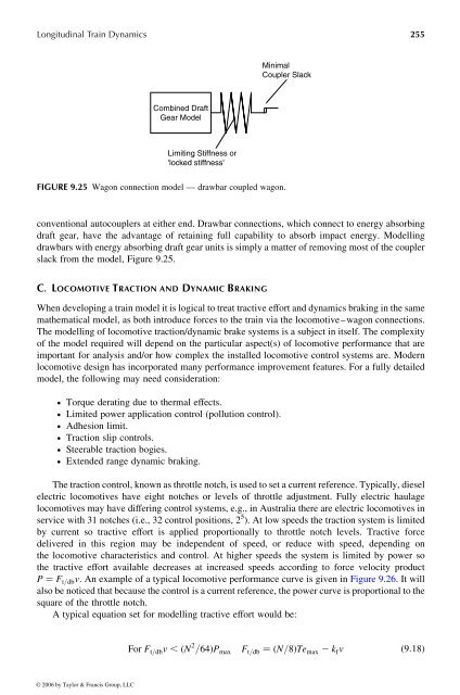
Longitudinal Train Dynamics 255<br />
Combined Draft<br />
Gear Model<br />
Limiting Stiffness or<br />
'locked stiffness'<br />
FIGURE 9.25 Wagon connection model —drawbar coupled wagon.<br />
conventional autocouplers at either end. Drawbar connections, which connect toenergy absorbing<br />
draft gear, have the advantage of retaining full capability to absorb impact energy. Modelling<br />
drawbarswith energy absorbing draft gear units is simplyamatter of removing mostofthe coupler<br />
slack from the model, Figure 9.25.<br />
C . L OCOMOTIVE T RACTION AND D YNAMIC B RAKING<br />
When developing atrain model it is logical to treat tractive effort and dynamics braking in the same<br />
mathematical model, as both introduce forces to the train via the locomotive–wagon connections.<br />
The modelling oflocomotive traction/dynamic brake systems is asubject in itself. The complexity<br />
of the model required will depend on the particular aspect(s) of locomotive performance that are<br />
important for analysis and/or how complex the installed locomotive control systems are. Modern<br />
locomotive design has incorporated many performance improvement features. For afully detailed<br />
model, the following may need consideration:<br />
† Torque derating due to thermal effects.<br />
† Limited power application control (pollution control).<br />
† Adhesion limit.<br />
† Traction slip controls.<br />
† Steerable traction bogies.<br />
† Extended range dynamic braking.<br />
Minimal<br />
Coupler Slack<br />
The traction control,knownasthrottle notch, is used to set acurrent reference. Typically, diesel<br />
electric locomotives have eight notches or levels of throttle adjustment. Fully electric haulage<br />
locomotives may have differing control systems, e.g., in Australia there are electric locomotives in<br />
service with 31 notches (i.e., 32 control positions, 2 5 ). At low speeds the traction system is limited<br />
by current so tractive effort is applied proportionally to throttle notch levels. Tractive force<br />
delivered in this region may be independent of speed, or reduce with speed, depending on<br />
the locomotive characteristics and control. At higher speeds the system is limited by power so<br />
the tractive effort available decreases at increased speeds according to force velocity product<br />
P ¼ F t = dbv : An example ofatypical locomotive performance curve is given in Figure 9.26. Itwill<br />
also be noticed that because the control is acurrent reference, the powercurve is proportional to the<br />
square of the throttle notch.<br />
Atypical equation set for modelling tractive effort would be:<br />
© 2006 by Taylor & Francis Group, LLC<br />
For F t = dbv , ð N 2 = 64Þ P max F t = db ¼ðN = 8 Þ Te max 2 k f v ð 9 : 18Þ