Hi-Res PDF - CRCnetBASE
Hi-Res PDF - CRCnetBASE
Hi-Res PDF - CRCnetBASE

Create successful ePaper yourself
Turn your PDF publications into a flip-book with our unique Google optimized e-Paper software.
Longitudinal Train Dynamics 259<br />
Braking Force, kN<br />
250<br />
200<br />
150<br />
100<br />
50<br />
0<br />
0 20 40 60 80 100 120<br />
Velocity, kph<br />
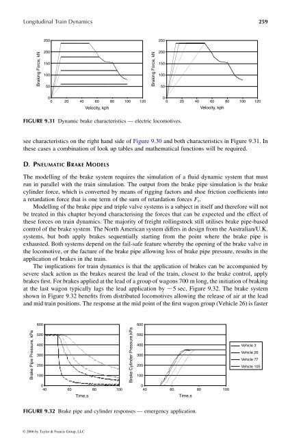
FIGURE 9.31 Dynamic brake characteristics —electric locomotives.<br />
see characteristics on the right hand side of Figure 9.30 and both characteristics inFigure 9.31. In<br />
these cases acombination of look up tables and mathematical functions will be required.<br />
D . P NEUMATIC B RAKE M ODELS<br />
0<br />
0 20 40 60 80 100 120<br />
The modelling of the brake system requires the simulation of afluid dynamic system that must<br />
run in parallel with the train simulation. The output from the brake pipe simulation is the brake<br />
cylinder force, which is converted bymeans of rigging factors and shoe friction coefficients into<br />
aretardation force that is one term of the sum of retardation forces F r .<br />
Modelling of the brake pipe and triple valvesystems is asubject in itselfand therefore will not<br />
be treated in this chapter beyond characterising the forces that can be expected and the effect of<br />
these forces on train dynamics. The majority of freight rollingstock still utilises brake pipe-based<br />
control of the brake system. The North Americansystem differs in design from the Australian/U.K.<br />
systems, but both apply brakes sequentially starting from the point where the brake pipe is<br />
exhausted. Both systems depend on the fail-safe feature whereby the opening of the brake valve in<br />
the locomotive, or the facture of the brake pipe allowing loss of brake pipe pressure, results in the<br />
application of brakes in the train.<br />
The implications for train dynamics is that the application of brakes can be accompanied by<br />
severe slack action as the brakes nearest the lead of the train, closest to the brake control, apply<br />
brakes first.For brakes applied at the leadofagroup of wagons 700 mlong, the initiationofbraking<br />
at the last wagon typically lags the lead application by , 5sec, Figure 9.32. The brake system<br />
shown in Figure 9.32 benefits from distributed locomotives allowing the release ofair at the lead<br />
and mid train positions. The response at the mid point of the first wagon group (Vehicle 26) is faster<br />
Brake Pipe Pressure, kPa<br />
600<br />
500<br />
400<br />
300<br />
200<br />
100<br />
0<br />
40 60 80 100<br />
Time,s<br />
Brake Cylinder Pressure,kPa<br />
600<br />
500<br />
400<br />
300<br />
200<br />
100<br />
Braking Force, kN<br />
250<br />
200<br />
150<br />
100<br />
50<br />
Velocity, kph<br />
0<br />
40 60 80 100<br />
Time,s<br />
FIGURE 9.32 Brake pipe and cylinder responses —emergency application.<br />
© 2006 by Taylor & Francis Group, LLC<br />
Vehicle 3<br />
Vehicle 26<br />
Vehicle 77<br />
Vehicle 105