Hi-Res PDF - CRCnetBASE
Hi-Res PDF - CRCnetBASE
Hi-Res PDF - CRCnetBASE

Create successful ePaper yourself
Turn your PDF publications into a flip-book with our unique Google optimized e-Paper software.
Longitudinal Train Dynamics 247<br />
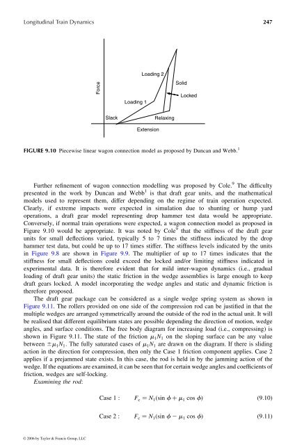
Force<br />
Slack<br />
Loading 1<br />
Loading 2<br />
Extension<br />
Relaxing<br />
Further refinement of wagon connection modelling was proposed by Cole. 9 The difficulty<br />
presented in the work by Duncan and Webb 1 is that draft gear units, and the mathematical<br />
models used to represent them, differ depending on the regime oftrain operation expected.<br />
Clearly, if extreme impacts were expected in simulation due to shunting or hump yard<br />
operations, a draft gear model representing drop hammer test data would be appropriate.<br />
Conversely, if normal train operations were expected, awagon connection model asproposed in<br />
Figure 9.10 would be appropriate. It was noted by Cole 9 that the stiffness ofthe draft gear<br />
units for small deflections varied, typically 5to 7times the stiffness indicated by the drop<br />
hammer test data, but could beupto17times stiffer. The stiffness levels indicated by the units<br />
in Figure 9.8 are shown in Figure 9.9. The multiplier of up to 17 times indicates that the<br />
stiffness for small deflections could exceed the locked and/or limiting stiffness indicated in<br />
experimental data. It is therefore evident that for mild inter-wagon dynamics (i.e., gradual<br />
loading of draft gear units) the static friction in the wedge assemblies is large enough to keep<br />
draft gears locked. Amodel incorporating the wedge angles and static and dynamic friction is<br />
therefore proposed.<br />
The draft gear package can be considered as asingle wedge spring system as shown in<br />
Figure 9.11. The rollers provided on one side of the compression rod can be justified in that the<br />
multiplewedges are arranged symmetrically around the outside of the rod in the actual unit. It will<br />
be realised that different equilibrium states are possible depending the direction of motion, wedge<br />
angles, and surface conditions. The free body diagram for increasing load (i.e., compressing) is<br />
shown in Figure 9.11. The state of the friction m 1 N 1 on the sloping surface can be any value<br />
between ^ m 1 N 1 : The fully saturated cases of m 1 N 1 are drawn onthe diagram. If there issliding<br />
action in the direction for compression, then only the Case 1friction component applies. Case 2<br />
applies if aprejammed state exists. In this case, the rod is held in by the jamming action of the<br />
wedge. If the equations are examined, it can be seen that for certainwedge angles and coefficients of<br />
friction, wedges are self-locking.<br />
Examining the rod:<br />
Solid<br />
Locked<br />
FIGURE 9.10 Piecewise linear wagon connection model as proposed by Duncan and Webb. 1<br />
© 2006 by Taylor & Francis Group, LLC<br />
Case 1 : F c ¼ N 1 ð sin f þ m 1 cos f Þ ð9 : 10Þ<br />
Case 2 : F c ¼ N 1 ð sin f 2 m 1 cos f Þ ð9 : 11Þ