Hi-Res PDF - CRCnetBASE
Hi-Res PDF - CRCnetBASE
Hi-Res PDF - CRCnetBASE

Create successful ePaper yourself
Turn your PDF publications into a flip-book with our unique Google optimized e-Paper software.
Longitudinal Train Dynamics 267<br />
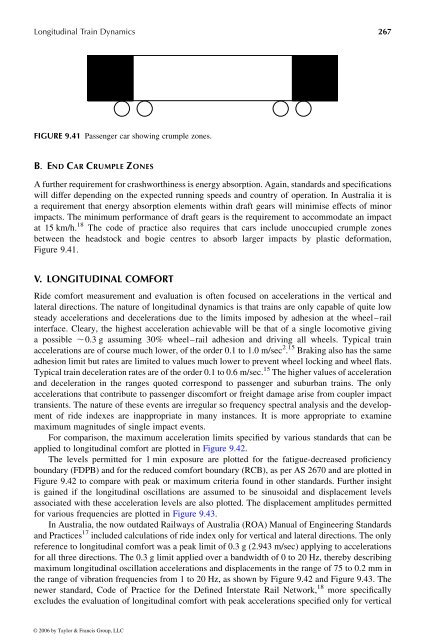
FIGURE 9.41 Passenger car showing crumple zones.<br />
B . E ND C AR C RUMPLE Z ONES<br />
Afurther requirement for crashworthiness is energy absorption. Again, standards and specifications<br />
will differ depending on the expected running speeds and country of operation. In Australia it is<br />
arequirement that energy absorption elements within draft gears will minimise effects of minor<br />
impacts. The minimum performance of draft gears is the requirement to accommodate an impact<br />
at 15 km/h. 18 The code of practice also requires that cars include unoccupied crumple zones<br />
between the headstock and bogie centres to absorb larger impacts by plastic deformation,<br />
Figure 9.41.<br />
V. LONGITUDINAL COMFORT<br />
Ride comfort measurement and evaluation is often focused on accelerations in the vertical and<br />
lateral directions. The nature of longitudinal dynamics is that trains are only capable of quite low<br />
steady accelerations and decelerations due to the limits imposed by adhesion at the wheel–rail<br />
interface. Cleary, the highest acceleration achievable will be that of asingle locomotive giving<br />
apossible , 0.3 gassuming 30% wheel–rail adhesion and driving all wheels. Typical train<br />
accelerations are of course muchlower,ofthe order 0.1 to 1.0 m/sec 2 . 15 Braking also has the same<br />
adhesion limit butrates are limited to values much lower to prevent wheel locking and wheel flats.<br />
Typical train deceleration rates are of the order 0.1 to 0.6 m/sec. 15 Thehighervalues of acceleration<br />
and deceleration in the ranges quoted correspond to passenger and suburban trains. The only<br />
accelerations that contribute to passenger discomfort orfreight damage arise from coupler impact<br />
transients. The nature of these events are irregular so frequency spectral analysis and the development<br />
of ride indexes are inappropriate in many instances. It is more appropriate to examine<br />
maximum magnitudes of single impact events.<br />
For comparison, the maximum acceleration limits specified by various standards that can be<br />
applied to longitudinal comfort are plotted in Figure 9.42.<br />
The levels permitted for 1min exposure are plotted for the fatigue-decreased proficiency<br />
boundary (FDPB) and for the reduced comfort boundary (RCB), as per AS 2670 and are plotted in<br />
Figure 9.42 to compare with peak or maximum criteria found in other standards. Further insight<br />
is gained if the longitudinal oscillations are assumed to be sinusoidal and displacement levels<br />
associated with these acceleration levels are also plotted. The displacement amplitudes permitted<br />
for various frequencies are plotted in Figure 9.43.<br />
In Australia, the now outdated Railways of Australia (ROA) ManualofEngineering Standards<br />
and Practices 17 includedcalculations of rideindexonly for vertical and lateral directions. Theonly<br />
reference to longitudinal comfort was apeak limit of 0.3 g(2.943 m/sec) applying to accelerations<br />
for all three directions. The 0.3 glimit applied over abandwidth of 0to20Hz, thereby describing<br />
maximum longitudinal oscillation accelerations and displacements in the range of 75 to 0.2 mm in<br />
the range of vibration frequencies from 1to20Hz, as shown byFigure 9.42 and Figure 9.43. The<br />
newer standard, Code ofPractice for the Defined Interstate Rail Network, 18 more specifically<br />
excludes the evaluation of longitudinal comfort with peak accelerations specified only for vertical<br />
© 2006 by Taylor & Francis Group, LLC