Hi-Res PDF - CRCnetBASE
Hi-Res PDF - CRCnetBASE
Hi-Res PDF - CRCnetBASE

You also want an ePaper? Increase the reach of your titles
YUMPU automatically turns print PDFs into web optimized ePapers that Google loves.
272<br />
Coupler Force, kN<br />
Coupler Force, kN<br />
400<br />
0<br />
- 400<br />
- 800<br />
400<br />
- 400<br />
- 800<br />
0 20 40 60 80 100<br />
Time,s<br />
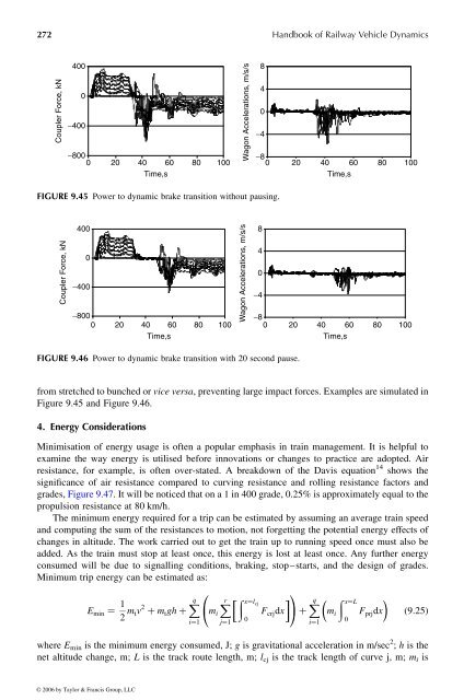
FIGURE 9.45 Power to dynamic brake transition without pausing.<br />
0<br />
0 20 40 60 80 100<br />
Time,s<br />
FIGURE 9.46 Power to dynamic brake transition with 20 second pause.<br />
from stretched to bunchedor vice versa ,preventing large impact forces. Examples are simulated in<br />
Figure 9.45 and Figure 9.46.<br />
4. Energy Considerations<br />
Minimisation of energy usage is often apopular emphasis in train management. It is helpful to<br />
examine the way energy is utilised before innovations or changes topractice are adopted. Air<br />
resistance, for example, is often over-stated. Abreakdown of the Davis equation 14 shows the<br />
significance of air resistance compared to curving resistance and rolling resistance factors and<br />
grades, Figure9.47.Itwill be noticed that on a1in 400 grade,0.25% is approximately equal to the<br />
propulsion resistance at80km/h.<br />
The minimum energy required for atrip can be estimated by assuming an average train speed<br />
and computing the sum of the resistances to motion, not forgetting the potential energy effects of<br />
changes inaltitude. The work carried out to get the train up to running speed once must also be<br />
added. As the train must stop at least once, this energy islost at least once. Any further energy<br />
consumed will be due to signalling conditions, braking, stop–starts, and the design of grades.<br />
Minimum trip energy can be estimated as:<br />
E min ¼ 1<br />
2 m t v 2 þ m t gh þ Xq<br />
i ¼ 1<br />
0<br />
@<br />
X<br />
m i<br />
r<br />
j ¼ 1<br />
1<br />
�ðx¼l �<br />
cj<br />
X<br />
F crjd x A þ q � ð x ¼ L �<br />
F prjd x<br />
0<br />
i ¼ 1<br />
m i<br />
0<br />
ð 9 : 25Þ<br />
where E min is the minimum energy consumed, J; g is gravitational acceleration in m/sec 2 ; h is the<br />
net altitude change, m; L is the track route length, m; l cj is the track length of curve j, m; m i is<br />
© 2006 by Taylor & Francis Group, LLC<br />
Wagon Accelerations, m/s/s<br />
Wagon Accelerations, m/s/s<br />
- 4<br />
- 8<br />
8<br />
4<br />
0<br />
- 4<br />
- 8<br />
8<br />
4<br />
0<br />
Handbook of Railway Vehicle Dynamics<br />
0 20 40 60 80 100<br />
Time,s<br />
0 20 40 60 80 100<br />
Time,s