Hi-Res PDF - CRCnetBASE
Hi-Res PDF - CRCnetBASE
Hi-Res PDF - CRCnetBASE

Create successful ePaper yourself
Turn your PDF publications into a flip-book with our unique Google optimized e-Paper software.
Longitudinal Train Dynamics 249<br />
If it is assumed that m 1 ¼ m 2 ; and that both surfaces are saturated, then the equation reduces to:<br />
F c ¼ F s ð m cot f þ 1 Þ = ð 1 þ m 2 Þ ð9 : 13Þ<br />
The other extreme ofpossibility is when there is no impending motion onthe sloping surface<br />
due to the seatingofthe rod and wedge, the value assumed for m 1 is zero, Equation 9.10 reducing to:<br />
F c ¼ F s tan f = ½ tan f 2 m 2 � ð9 : 14Þ<br />
If the same analysis isrepeated for the unloading case, asimilar equation results,<br />
F c ¼ F s tan f = ½ tan f þ m 2 � ð9 : 15Þ<br />
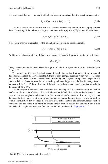
At this point, it is convenient to define anew parameter, namely friction wedge factor, as follows:<br />
Q ¼ F c = F s<br />
ð 9 : 16Þ<br />
Using the new parameter, the two relationships 9.13 and 9.14 are plotted for various values of f in<br />
Figure 9.13.<br />
The above plots illustrate the significance of the sloping surface friction condition. Measured<br />
data indicated in Ref. 19 showed that the stiffness of draft gear packages can reach values , 7times<br />
the values obtained in drop hammer tests. Assuming the polymer spring force displacement<br />
characteristic is of median slope between loading and unloading curves, the friction wedge factor<br />
requiredwill be Q , 15. From disassembled draft gear packages, wedge angles are knowntobein<br />
the range of 30 to 508 .<br />
The only aspect of the modelthat now remains to be completed is the behaviour of the friction<br />
coefficient. Estimation of these values will always be difficult due to the variable nature of the<br />
surfaces. Surface roughness and wear ensurethat the actual coefficients of friction can vary, even on<br />
the same draft gear unit, resulting in different responses to drop hammer tests. It is also difficult to<br />
estimatethe function that describes the transition zone betweenstatic and minimum kinetic friction<br />
conditions and the velocity at which minimum kinetic friction occurs. For simplicity and afirst<br />
approximation, apiece-wise-linear function can be used as shown inFigure 9.14.<br />
F c / F s<br />
FIGURE 9.13 Friction wedge factor for m ¼ 0.5.<br />
© 2006 by Taylor & Francis Group, LLC<br />
20<br />
15<br />
10<br />
5<br />
Both Surfaces Saturated<br />
0<br />
0 20 40 60 80<br />
Wedge Angle, Degrees<br />
No Friction on Sloping Surface