Hi-Res PDF - CRCnetBASE
Hi-Res PDF - CRCnetBASE
Hi-Res PDF - CRCnetBASE

You also want an ePaper? Increase the reach of your titles
YUMPU automatically turns print PDFs into web optimized ePapers that Google loves.
274<br />
Coupler<br />
Force<br />
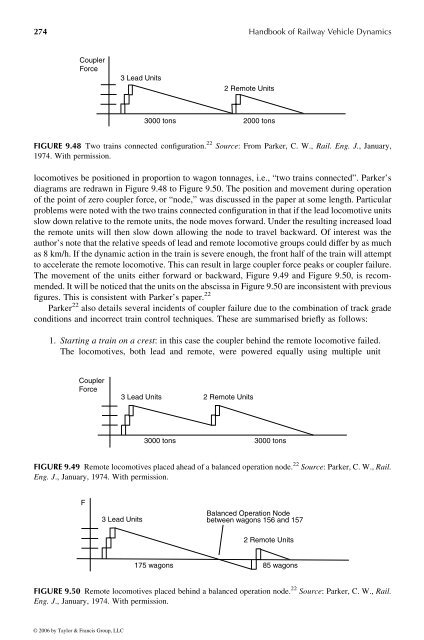
locomotives be positioned in proportion to wagon tonnages, i.e., “two trains connected”. Parker’s<br />
diagrams are redrawn in Figure 9.48 to Figure 9.50. The position and movement during operation<br />
of the point of zero coupler force, or “node,” was discussed in the paper at some length. Particular<br />
problemswere notedwith the two trains connected configuration in that if the lead locomotive units<br />
slow down relative to the remoteunits, the node moves forward. Underthe resulting increased load<br />
the remote units will then slow down allowing the node to travel backward. Of interest was the<br />
author’s note that the relative speedsoflead and remotelocomotive groups coulddiffer by as much<br />
as 8km/h. If the dynamic action in the train is severeenough, the front half of the train will attempt<br />
to accelerate the remotelocomotive. This can result in large coupler force peaks or coupler failure.<br />
The movement of the units either forward orbackward, Figure 9.49 and Figure 9.50, is recommended.<br />
It will be noticed that the units on the abscissa in Figure 9.50are inconsistent with previous<br />
figures. This is consistent with Parker’s paper. 22<br />
Parker 22 also details several incidents of coupler failure due to the combination of track grade<br />
conditions and incorrect train control techniques. These are summarised briefly as follows:<br />
1. Starting atrain on acrest: inthis case the coupler behind the remote locomotive failed.<br />
The locomotives, both lead and remote, were powered equally using multiple unit<br />
Coupler<br />
Force<br />
3Lead Units<br />
3000 tons<br />
2Remote Units<br />
3Lead Units 2Remote Units<br />
2000 tons<br />
FIGURE 9.48 Two trains connected configuration. 22 Source: From Parker, C. W., Rail. Eng. J., January,<br />
1974. With permission.<br />
3000 tons 3000 tons<br />
FIGURE 9.49 Remote locomotives placed ahead of abalanced operation node. 22 Source:Parker, C. W., Rail.<br />
Eng. J ., January, 1974. With permission.<br />
F<br />
3Lead Units<br />
Balanced Operation Node<br />
between wagons 156 and 157<br />
2Remote Units<br />
175 wagons 85 wagons<br />
Handbook of Railway Vehicle Dynamics<br />
FIGURE 9.50 Remote locomotives placed behind abalanced operation node. 22 Source: Parker, C. W., Rail.<br />
Eng. J ., January, 1974. With permission.<br />
© 2006 by Taylor & Francis Group, LLC