You also want an ePaper? Increase the reach of your titles
YUMPU automatically turns print PDFs into web optimized ePapers that Google loves.
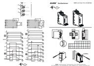
Wiring<br />
Refer to application diagrams that display the logic controlling the isolation device via the detected fault relay.<br />
System Grounding<br />
If system grounding is not adequate to handle ground trip levels which can exceed 1300% of motor full load amps (Motor FLA), then this<br />
device may not protect the branch circuit conductors. In this case, external ground trip protection must be properly coordinated.<br />
Recommended solutions include:<br />
• Time delay fuses coordinated to 125% of motor FLA. The fuses listed in the chapter Branch circuit protection are sized to provide<br />
proper coordination and may be used for applications that do not require start times longer than 50 seconds at 300% current limit or<br />
20 seconds at 500% current limit.<br />
• External overload relay. For multi-motor applications, applications in which motor does not match the soft starter size, or applications<br />
that use a full voltage bypass scheme, an external overload relay can be coordinated to protect conductors from a high-impedance<br />
ground trip.<br />
General wiring practices<br />
When wiring SH31 soft starter, follow the wiring practices required by national and local electrical codes. In addition, follow these<br />
guidelines:<br />
• Use metallic conduit for all soft starter wiring. Do not run control and power wiring in the same conduit.<br />
• Separate metallic conduits carrying power wiring or low-level control wiring by at least 80 mm (3 in).<br />
• Separate non-metallic conduits or cable trays used to carry power wiring from metallic conduit carrying low-level control wiring by at<br />
least 305 mm (12 in).<br />
• Always cross power and control wiring at right angles.<br />
• Keep the control circuits away from the power cables.<br />
Adaptation to line input<br />
The control circuit is completely independent of the power circuit. To apply control voltage, follow the instructions on the label located on<br />
the soft starter terminal strip. Connect single phase voltage of 110 or 230 Vac supply to terminals CL1 and CL2.<br />
The power circuit adapts automatically to the input line voltage and frequency over a range of 230 to 440 V for SH31-.../4 soft starters, and<br />
over a range of 208 to 600 V for SH31-.../6 soft starters.<br />
28<br />
MOTOR OVERHEATING HAZARD<br />
CAUTION<br />
If the solid-state switches on the SH31 become inoperable, single-phase operation of the motor can result.<br />
• Use an isolation device consisting of either a circuit breaker equipped with a shunt trip coil or an electromagnetic contactor to open<br />
the line-side of the soft starter.<br />
• The isolation device must be capable of interrupting the motor locked rotor current.<br />
• Connect the detected fault relay of the soft starter to open the isolation device in the event of a soft starter trip.<br />
Failure to follow these instructions can result in injury or equipment damage.<br />
WARNING<br />
INADEQUATE SYSTEM GROUNDING- BRANCH CIRCUIT CONDUCTOR HAZARD<br />
If system grounding is not adequate for ground fault levels, use properly coordinated external ground fault protection. Possible solutions<br />
include:<br />
• Time delay fuses coordinated to 125% of motor FLA.<br />
• A properly coordinated external overload relay.<br />
Failure to follow these instructions can result in death, serious injury, or equipment damage.