
You also want an ePaper? Increase the reach of your titles
YUMPU automatically turns print PDFs into web optimized ePapers that Google loves.
Display terminal<br />
LED’s display<br />
The front cover of the control board contains four LEDs above the seven segment display that display the SH31 status and activity.<br />
Name Location Description<br />
Rdy Green - front cover<br />
Com Green - front cover<br />
Run Yellow - front cover<br />
Trip Red - front cover<br />
NOTE: see LED parameter, page 78.<br />
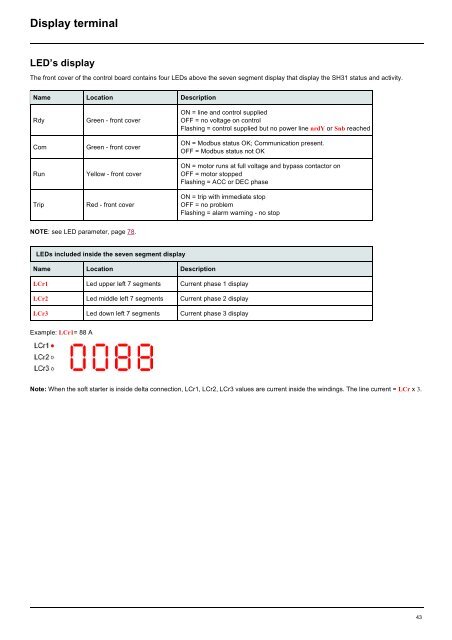
LEDs included inside the seven segment display<br />
Name Location Description<br />
Example: LCr1= 88 A<br />
ON = line and control supplied<br />
OFF = no voltage on control<br />
Flashing = control supplied but no power line nrdY or Snb reached<br />
ON = Modbus status OK; Communication present.<br />
OFF = Modbus status not OK<br />
ON = motor runs at full voltage and bypass contactor on<br />
OFF = motor stopped<br />
Flashing = ACC or DEC phase<br />
ON = trip with immediate stop<br />
OFF = no problem<br />
Flashing = alarm warning - no stop<br />
LCr1 Led upper left 7 segments Current phase 1 display<br />
LCr2 Led middle left 7 segments Current phase 2 display<br />
LCr3 Led down left 7 segments Current phase 3 display<br />
Note: When the soft starter is inside delta connection, LCr1, LCr2, LCr3 values are current inside the windings. The line current = LCr x 3.<br />
43