

Transactions
Transactions
Transactions

Create successful ePaper yourself
Turn your PDF publications into a flip-book with our unique Google optimized e-Paper software.
MAYERS—FLOW PROCESSES IN U N D ERFEED STOKERS 487<br />
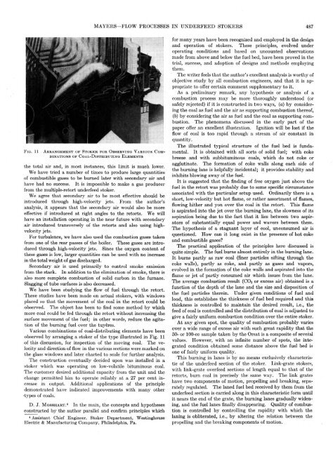
F i g . 11 A r r a n g e m e n t o f S t o k e r f o r O b s e r v i n g V a r i o u s C o m <br />
b i n a t i o n s o f C o a l - D i s t r i b u t i n g E l e m e n t s<br />
the total air and, in most instances, this limit is much lower.<br />
We have tried a number of times to produce large quantities<br />
of combustible gases to be burned later with secondary air and<br />
have had no success. It is impossible to make a gas producer<br />
from the multiple-retort underfeed stoker.<br />
We agree that secondary air to be most effective should be<br />
introduced through high-velocity jets. From the author’s<br />
analysis, it appears that the secondary air would also be more<br />
effective if introduced at right angles to the retorts. We will<br />
have an installation operating in the near future with secondary<br />
air introduced transversely of the retorts and also using highvelocity<br />
jets.<br />
For turbulence, we have also used the combustion gases taken<br />
from one of the rear passes of the boiler. These gases are introduced<br />
through high-velocity jets. Since the oxygen content of<br />
these gases is low, larger quantities can be used with no increase<br />
in the total weight of gas discharged.<br />
Secondary air is used primarily to control smoke emission<br />
from the stack. In addition to the elimination of smoke, there is<br />
also more complete combustion of solid carbon in the furnace.<br />
Slagging of tube surfaces is also decreased.<br />
We have been studying the flow of fuel through the retort.<br />
These studies have been made on actual stokers, with windows<br />
placed so that the movement of the coal in the retort could be<br />
observed. The object has been to find some method by which<br />
more coal could be fed through the retort without increasing the<br />
surface movement of the fuel; in other words, reduce the agitation<br />
of the burning fuel over the tuyeres.<br />
Various combinations of coal-distributing elements have been<br />
observed by arranging a stoker of the type illustrated in Fig. 11<br />
of this discussion, for inspection of the moving coal. The velocity<br />
and direction of flow in the various sections were marked on<br />
the glass windows and later charted to scale for further analysis.<br />
The construction eventually decided upon was installed in a<br />
stoker which was operating on low-volatile bituminous coal.<br />
The customer desired additional capacity from the unit and the<br />
change permitted him to operate reliably at a 27 per cent increase<br />
in output. Additional applications of the principle<br />
demonstrated have indicated improvements with many other<br />
•types of coals.<br />
D. J. M o s s h a r t . 4 In the main, the concepts and hypotheses<br />
constructed by the author parallel and confirm principles which<br />
4 Assistant Chief Engineer, Stoker Department, Westinghouse<br />
Electric & Manufacturing Company, Philadelphia, Pa.<br />
for many years have been recognized and employed in the design<br />
and operation of stokers. These principles, evolved under<br />
operating conditions and based on uncounted observations<br />
made from above and below the fuel bed, have been proved in the<br />
trial, success, and adoption of designs and methods employing<br />
them.<br />
The writer feels that the author’s excellent analysis is worthy of<br />
objective study by all combustion engineers, and that it is appropriate<br />
to offer certain comment supplementary to it.<br />
As a preliminary remark, any hypothesis or analysis of a<br />
combustion process may be more thoroughly understood (or<br />
safely rejected) if it is constructed in two ways, (a) by considering<br />
the coal as fuel and the air as supporting combustion thereof,<br />
(6) by considering the air as fuel and the coal as supporting combustion.<br />
The phenomena discussed in the early part of the<br />
paper offer an excellent illustration. Ignition will be lost if the<br />
flow of coal is too rapid through a stream of air constant in<br />
quantity.<br />
The illustrated typical structure of the fuel bed is fundamental.<br />
I t is obtained with all sorts of solid fuel; with coke<br />
breeze and with subbituminous coals, which do not coke or<br />
agglutinate. The formation of coke walls along each side of<br />
the burning lane is helpfully incidental; it provides stability and<br />
inhibits blowing away of the fuel.<br />
It is suggested that the finding of free oxygen just above the<br />
fuel in the retort was probably due to some specific circumstance<br />
associated with the particular setup used. Ordinarily there is a<br />
short, low'-velocity but hot flame, or rather assortment of flames,<br />
flowing hither and yon over the coal in the retort. This flame<br />
is aspirated into the jet over the burning lane, the slowness of its<br />
aspiration being due to the fact that it lies between two aspirators<br />
of substantially equal power and wavers between them.<br />
The hypothesis of a stagnant layer of cool, unconsumed air is<br />
questioned. How can it long exist in the presence of hot coke<br />
and combustible gases?<br />
The practical application of the principles here discussed is<br />
quite simple. The fuel burns almost entirely in the burning lane.<br />
It burns partly as raw coal (finer particles sifting through the<br />
coke walls), partly as coke, and partly as gases and vapors,<br />
evolved in the formation of the coke walls and aspirated into the<br />
flame or jet of partly consumed air which issues from the lane.<br />
The average combustion result (C02 or excess air) obtained is a<br />
function of the depth of the lane and the size and disposition of<br />
the fuel particles therein. Under given conditions of fuel and<br />
load, this establishes the thickness of fuel bed required and this<br />
thickness is controlled to maintain the desired result, i.e., the<br />
feed of coal is controlled and the distribution of coal is adjusted to<br />
give a fairly uniform combustion condition over the entire stoker.<br />
At any given spot, the quality of combustion probably varies<br />
over a wide range of excess air with such great rapidity that the<br />
50- or 100-cc sample taken by the Orsat is a composite of several<br />
values. However, with an infinite number of spots, the integrated<br />
condition obtained some distance above the fuel bed is<br />
one of fairly uniform quality.<br />
This burning in lanes is by no means exclusively characteristic<br />
of the underfeed section of the stoker. Link-grate stokers,<br />
with link-grate overfeed sections of length equal to that of the<br />
retorts, burn coal in precisely the same way. The link grates<br />
have two components of motion, propelling and breaking, separately<br />
regulated. The laned fuel bed received by them from the<br />
underfeed section is carried along in this characteristic form until<br />
it nears the end of the grate, the burning lanes gradually widening,<br />
and the fuel lanes finally disappearing. Quality of combustion<br />
is controlled by controlling the rapidity with which the<br />
laning is obliterated, i.e., by altering the relation between the<br />
propelling and the breaking components of motion.


