

Transactions
Transactions
Transactions

You also want an ePaper? Increase the reach of your titles
YUMPU automatically turns print PDFs into web optimized ePapers that Google loves.
The differential equations for the thermal circuit (and of the<br />
thermal system) and those of an analogous electrical circuit<br />
follow:<br />
BECK—TH ERM O M ETRIC TIM E LAG 541<br />
q — thermal current, Btu per hr<br />
e = instantaneous voltage of angular frequency a<br />
applied to condenser C and resistor R in series<br />
i = electrical current<br />
i = V —i<br />
The instantaneous temperature t, measured by the thermometric<br />
element (measured above the same mean as r) corresponds<br />
to the voltage across the capacitor C. Thus<br />
where / = unit conductance between the fluid and the thermometer<br />
A t = difference in temperature between fluid and thermometer<br />
at any time 0 after the sudden change in<br />
the fluid temperature (or immersion of the thermometer<br />
in a fluid of fixed temperature)<br />
A t o — initial difference in temperature between thermometer<br />
and fluid<br />
A = area through which heat flows to immersed portion<br />
of thermometer<br />
V = volume of immersed portion of thermometer<br />
y = weight per unit volume of immersed portion of<br />
thermometer<br />
Cp = unit heat capacity of immersed portion of thermometer<br />
e = voltage in electrical circuit corresponding to temperature<br />
in thermal circuit, i.e., voltage across<br />
resistor B<br />
Co = initial voltage drop across resistor R<br />
By definition:<br />
L — time constant (lag) = RC =<br />
VyCP<br />
fA<br />
The quantity VyCp depends only upon the construction of the<br />
thermometer (thermocouple) and the degree of immersion and<br />
may be tabulated for any instrument by the manufacturer.<br />
The unit conductance / is a function of the method of application<br />
of the instrument, i.e., the fluid properties and the character of<br />
the flow over the thermometric element. The unit conductance<br />
may vary a thousandfold for different applications. The<br />
manufacturer should tabulate typical magnitudes of the unit<br />
conductance for common applications. Users of thermometers<br />
can then readily compute the performance of any instrument<br />
under transient conditions.<br />
More complex ideal systems, involving distributed capacities<br />
and resistances, may be devised more accurately to predict the<br />
behavior of a thermometric element. Further, more complicated<br />
thermometric elements may be treated analytically (the<br />
analogous electrical circuits for which solutions are available<br />
may be utilized).<br />
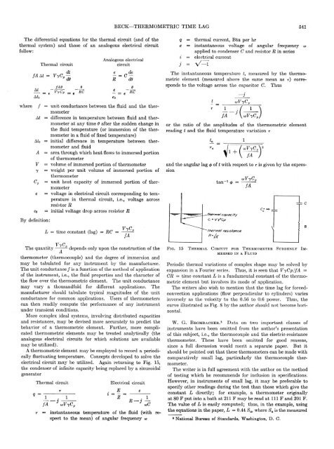
A thermometric element may be employed to record a periodically<br />
fluctuating temperature. Concepts developed to solve the<br />
electrical circuit may be utilized. Again returning to Fig. 15,<br />
the condenser of infinite capacity being replaced by a sinusoidal<br />
generator<br />
Thermal circuit<br />
E l e c t r i c a l c i r c u i t<br />
r = instantaneous temperature of the fluid (with respect<br />
to the mean) of angular frequency a<br />
or the ratio of the amplitudes of the thermometric element<br />
reading t and the fluid temperature variation r<br />
and the angular lag of t with respect to r is given by the expression<br />
F i g . 1 5 T h e r m a l C i r c u i t f o r T h e r m o m e t e r S u d d e n l y I m <br />
m e r s e d i n A F l u i d<br />
Periodic thermal variations of complex shape may be solved by<br />
expansion in a Fourier series. Thus, it is seen that VyCp/fA =<br />
CR — time constant L is a fundamental constant of the thermometric<br />
element but involves its mode of application.<br />
The writers also wish to mention that the time lag for forcedconvection<br />
applications (flow perpendicular to cylinders) varies<br />
inversely as the velocity to the 0.56 to 0.6 power. Thus, the<br />
curve illustrated as Fig. 8 by the author should not become horizontal.<br />
W. G. Brombacher.8 D ata on two im portant classes of<br />
instruments have been omitted from the author’s presentation<br />
of this subject, i.e., the thermocouple and the electric-resistance<br />
thermometer. These have been omitted for good reasons,<br />
since a full discussion would merit a separate paper. But it<br />
should be pointed out that these thermometers can be made with<br />
comparatively small lag, particularly the thermocouple thermometer.<br />
The writer is in full agreement with the author on the method<br />
of testing which he recommends for inclusion in specifications.<br />
However, in instruments of small lag, it m ay be preferable to<br />
specify other readings during the test than those which give the<br />
constant L directly; for example, a thermometer originally<br />
at 80 F put into a bath at 211 F may be read at 111 F and 201 F.<br />
The value of L is easily computed; thus, in the example, using<br />
the equations in the paper, L = 0.44 Sa, where Sa is the measured<br />
* National Bureau of Standards, Washington, D . C.


