

Transactions
Transactions
Transactions

Create successful ePaper yourself
Turn your PDF publications into a flip-book with our unique Google optimized e-Paper software.
536 TRANSACTIONS OF TH E A.S.M.E. AUGUST, 1941<br />
T i m e L a g o p I n d u s t r ia l M e r c u r y -i n -G l a s s T h e r m o m e t e r s<br />
The protecting well for the glass bulb usually has a diameter of<br />
*/« to 7/» in- and, if the space between bulb and well is properly<br />
filled with mercury, the time lag should be between 3 and 4 sec<br />
in well-agitated water. The separable socket with tapered fit approximately<br />
doubles the time lag; figures of 7.5 to 8.5 sec have<br />
been observed in water. It should be noted that, due to the tapered<br />
fit, the time lag is only slightly more than doubled; whereas,<br />
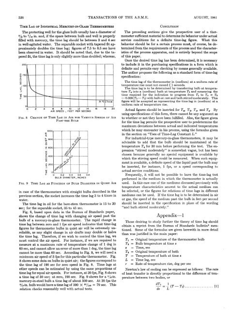
F i g . 8<br />
F i g . 9<br />
C h a n g e o f T i m e L a g i n A i r f o r V a r i o u s S p e e d s o f A i r<br />
P a s t t h e B u l b<br />
T im e L a g a s F u n c t i o n o f B u l b D i a m e t e r i n Q u i e t A ir<br />
in case of the thermometers with straight bulbs described in the<br />
previous section, the socket increases the time lag 3 to 4 times in<br />
water.<br />
The time lag in oil for the bare-stem thermometer is 15 to 20<br />
sec; for the separable socket, 35 to 45 sec.<br />
Fig. 8, based upon data in the Bureau of Standards paper,<br />
shows the change of time lag with changing air speed past the<br />
bulb of a mercury-in-glass thermometer. The rapid change in<br />
time lag between zero and 1 fps air speed indicates that time-lag<br />
figures for thermometer bulbs in quiet air will be extremely unreliable,<br />
as any slight change in air drafts may double or halve<br />
the time lag. Therefore, if we wish to control the time lag, we<br />
must control the air speed. For instance, if we are required to<br />
measure at a maximum rate of temperature change of 1 deg in<br />
60 sec, and cannot allow an error of more than 1 deg, the time lag<br />
cannot be more than 60 sec. According to Fig. 8, we will need a<br />
minimum air speed of 3 fps for this particular thermometer. Fig.<br />
8 shows some data on bulbs in quiet air; the figures correspond to<br />
the time lag of 190 sec for zero speed in Fig. 8. Time lags at<br />
other speeds can be estimated by using the same proportions of<br />
time lag for equal air speeds. For instance, at 20 fps, Fig. 8 shows<br />
a time lag of 30 sec; at zero, 190 sec. Fig. 9 shows for a 3/ s-in.<br />
mercury-in-steel bulb a time lag of about 500 sec. At 20 fps the<br />
‘/s-in. bulb would have a time lag of 500 X 3% 9o = 79 sec. This<br />
relation checks reasonably well with actual tests.<br />
C o n c l u s io n<br />
The preceding sections give the prospective user of a thermometer<br />
sufficient material to determine its behavior under actual<br />
service conditions for a definite time-lag figure. What this<br />
behavior should be for a certain process must, of course, be determined<br />
from the requirements of the process and the characteristics<br />
of the process apparatus, and is entirely beyond the scope<br />
of this paper.<br />
Once the desired time lag has been determined, it is necessary<br />
to include it in the purchasing specifications in a form which is<br />
definite and permits easy checking by means generally available.<br />
The author proposes the following as a standard form of time-lag<br />
specification:<br />
The time lag of the thermometer in (medium) at a uniform rate of<br />
temperature rise must not exceed ( ) seconds.<br />
The time lag is to be determined by transferring bulb at temperature<br />
T„ into a (medium) bath at temperature and measuring the<br />
time required for the indication to progress from T, to T , = Ti,<br />
— 0.368(Ti — T,) with bulb at rest and bath stirred moderately. This<br />
figure will be accepted as representing the time lag in (medium) at a<br />
uniform rate of temperature rise.<br />
Actual figures should be inserted for Ta, Tb, T„ and T,. By<br />
using specifications of this form, there cannot be any argument as<br />
to whether or not they have been fulfilled. Also, the figure given<br />
for the time lag permits the prospective user to predetermine the<br />
maximum deviations between actual and indicated temperatures<br />
which he may encounter in his process, using the formulas given<br />
in the section on “Uses of Time-Lag Constant L .”<br />
For industrial-type mercury-in-glass thermometers, it may be<br />
advisable to add that the bulb should be maintained at the<br />
temperature T b for 30 min before performing the test. The expression<br />
“stirred moderately” is somewhat vague, but has been<br />
chosen because generally no special equipment is available by<br />
which the stirring speed could be measured. When such equipment<br />
is available, a definite speed of the liquid past the bulb may<br />
be inserted, for instance, 1 fps, or a speed corresponding to<br />
actual service conditions.<br />
Frequently, it will not be possible to have the time-lag test<br />
performed in the medium in which the thermometer is actually<br />
used. In this case one of the mediums discussed previously with<br />
temperature characteristics nearest to the actual medium can<br />
be selected, or the figures for relations of time lags in different<br />
mediums can be used. If the time lag is to be determined in air<br />
or gas, the speed of the medium past the bulb in feet per second<br />
should be inserted in the specification in place of the wording<br />
“and bath stirred moderately.”<br />
Appendix— 1<br />
Those desiring to study further the theory of time lag should<br />
obtain a reprint from the Bureau of Standards bulletin2 mentioned.<br />
Some of the formulas are given herewith in more detail<br />
than was justified in the main paper:<br />
Ti = Original temperature of the thermometer bulb<br />
Ti = Bulb temperature at time s<br />
s = Time, sec<br />
T„ — Original temperature of bath<br />
T = Temperature of bath at time s<br />
L = Time lag, sec<br />
r = Rate of temperature rise, deg per sec<br />
Newton’s law of cooling can be expressed as follows: The rate<br />
of heat transfer is directly proportional to the difference of temperature<br />
between two bodies, or


