

Transactions
Transactions
Transactions

Create successful ePaper yourself
Turn your PDF publications into a flip-book with our unique Google optimized e-Paper software.
502 TRANSACTIONS OF TH E A.S.M.E. AUGUST, 1941<br />
stresses must be conservative and material m ust be high-strength<br />
steel. A factor of safety of approximately 12 to 13, based on the<br />
ultimate strength of the steel, is recommended.<br />
The wings of the saddle type of connecting rod, through which<br />
the wristpin bolts pass, are partly held at their sides. However,<br />
to simplify the method of calculating the depth required, it is<br />
convenient to consider them as simple cantilever beams with the<br />
bolt load as the applied load. The length of the cantilever beam<br />
is the distance y shown in Fig. 1. Bending stress at the junction<br />
of the cantilever and the main shank of the connecting rod should<br />
not be more than the ultimate strength divided by about 10.<br />
For the main-column section of the connecting rod, three<br />
cross-sectional types are used: I-beam, round, and rectangular.<br />
The minimum area of any cross section should be such that<br />
the compression stress per square inch of area from peak cylinder<br />
load is not more than the ultimate strength of the steel divided by<br />
approximately 7.<br />
In addition to direct stress on the minimum cross-sectional area,<br />
the connecting rod is a column and should be designed for safe<br />
stress as a column. When bending in the plane of the crankshaft<br />
center line, both ends of the column are considered fixed,<br />
with the column length as the distance from the crankpin center<br />
line to the wristpin center line, Fig. 3(6). Rankine’s formula for<br />
short columns has been found to be the most satisfactory, as<br />
very rarely is the l/r ratio of connecting rods greater than 120.<br />
When bending in a plane 90 deg to the crankshaft center line,<br />
the ends of the rod are considered free, Fig. 3(a). Thus, in the<br />
latter direction, the cross section of the rod must be designed with<br />
a greater radius of gyration r than in the other direction. Rankine’s<br />
formula for short columns is<br />
Sc = (PM )[1 + K l/rY).............................[6]<br />
where P = total thrust load on rod, lb; A = cross-sectional area<br />
at mid-point of rod, sq in.; k = 0.00004 for columns of fixed<br />
ends; k = 0.00016 for columns with free ends; I = length of rod<br />
from center line of crankpin to center line of wristpin, in.; r =<br />
radius of gyration of mid-point cross section in the direction that<br />
bending is being considered, in.; and Sc = column stress, psi.<br />
The latter value should not exceed the ultimate tensile strength of<br />
the material divided by a factor of safety 6.5.<br />
Using this method of design, it is quite obvious that the maximum<br />
stiffness and strength, with the minimum weight of material,<br />
is obtained by the use of I-beam cross-sectional shapes with the<br />
long axis of the I-beam in the plane 90 deg to the crankshaft<br />
center line. On some types and sizes of engines, where a low rate<br />
of production does not warrant the expense of dies for forging<br />
the I-beam section, it is more economical to use either the round<br />
or rectangular shape.<br />
The crankpin end of the connecting rod must be made stiff to<br />
prevent bending of the bolts holding the cap, and to prevent deflection<br />
of the crankpin-bearing shell. Most failures of crankpinbearing<br />
bolts and some failures of crankpin bearings may be<br />
attributed to the lack of stiffness in this end of the connecting<br />
rod. It is impractical to state the maximum allowable deflection<br />
in this end of the rod as this must be judged mostly by experience<br />
obtained from previous designs. The ideal deflection would, of<br />
•course, be zero which is obviously impossible.<br />
The flanges of the I-beam of the connecting-rod shank should<br />
be extended right to the bearing-shell backing to help stiffen the<br />
support for the bearing, as shown in Fig. 1. The angular cross<br />
section on approximately a radius from the center line of a<br />
crankpin bearing to the curve where the rod flares out to form<br />
seats for the bolts should also be of I-beam cross section for greatest<br />
rigidity with minimum weight. The bolts should be fitted<br />
a t the joint between the rod foot and the connecting-rod-bearing<br />
cap, or heavy closely fitted dowels should be used.<br />
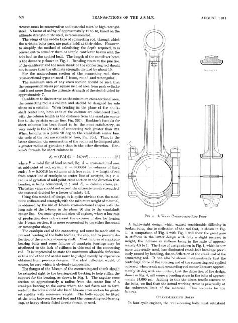
F i g . 4<br />
A W e a k C o n n e c t i n g - R o d F o o t<br />
A lightweight design which caused considerable difficulty in<br />
broken bolts, due to deflection of the rod foot, is shown in Fig.<br />
4. A comparison of Fig. 4 with Fig. 1 will show the great gain<br />
in stiffness in the latter design with only a slight increase in<br />
weight, the increase in stiffness being in the ratio of approximately<br />
4.5 to 1. The type of design shown in Fig. 1, which is now<br />
more universally used, has eliminated crank-bolt breakage previously<br />
caused by bending, due to deflection of the crank end of the<br />
connecting rod. It can also be shown mathematically that the<br />
centrifugal force of the rotating end of the connecting rod applied<br />
outward, when crank and connecting-rod center lines are approximately<br />
90 deg with each other, that the deflection of the design,<br />
shown in Fig. 4, will cause a bending stress in the bolts of approximately<br />
34,000 psi. Adding to this the direct tensile stresses on<br />
the bolts, we find that the actual working stress is practically at<br />
the endurance limit of the material. This accounts for the<br />
failures.<br />
C r a n k - B e a r in g B o l t s<br />
In four-cycle engines, the crank-bearing bolts must withstand


