

Transactions
Transactions
Transactions

You also want an ePaper? Increase the reach of your titles
YUMPU automatically turns print PDFs into web optimized ePapers that Google loves.
556 TRANSACTIONS OF TH E A.S.M.E. AUGUST, 1941<br />
solid. While the relationship need not and cannot be mathematically<br />
constant, the higher test stresses should not be assigned<br />
to the springs of lower solid stress.<br />
The higher solid stresses are produced by removal of permanent<br />
set, i.e., by cold-working the springs; and this cold-working<br />
has a marked effect on the endurance. The ideal condition for<br />
the tests would be a group of springs with graded solid stresses,<br />
produced without cold-working; but this is obviously impossible.<br />
The logical alternative is to maintain a relation between the test<br />
stress and the solid stress, and so between the test stress and the<br />
cold-working effect.<br />
The individual test stresses having been assigned, the test loads<br />
are calculated therefrom, by the formula<br />
T A B L E 3<br />
C A L C U L A T IO N F O R P R O B A B L E S-N C U R V E ; G R O U P E<br />
Each spring is then compressed under its test load in a testing<br />
machine, and the height accurately measured with the micrometer<br />
height gage. The springs are then ready for the fatigue test.<br />
C o n d u c t o f F a t ig u e T e s t<br />
The machine used for the fatigue test should be of sturdy and<br />
rigid construction, so that the cyclic deflection impressed on the<br />
springs will be accurate and uniform. Speed should not be so<br />
high, nor the stroke so great, as to cause impact stresses. Geared<br />
presses of the type suitable for this work usually run about 40 to<br />
70 strokes per min, and the higher speed is not excessive for the<br />
purpose. A stroke of not more than twice the spring deflection is<br />
believed to be satisfactory. If possible, the machine should be<br />
equipped with a screw adjustm ent in the spring support, so that<br />
the rig can be accurately adjusted to give the desired deflection to<br />
the spring.<br />
To set up a spring for the test, the machine is turned over until<br />
the ram is at the lowest point of its stroke, and the screw adjustment<br />
manipulated until the distance between ram and spring support<br />
corresponds to the “height under test load,” described in a<br />
previous section. The ram is then raised, the spring mounted on<br />
the support, which should be shouldered to position the spring<br />
centrally under the ram, the machine again turned over to its<br />
lower center, and the compressed height of the spring checked.<br />
The revolution counter is then set to zero or the initial reading<br />
recorded, and the test run started. The run on each spring should<br />
be as nearly continuous as is practicable. The machine on which<br />
recent Committee tests have been conducted is equipped with a<br />
photocell, which shuts down the machine when the spring breaks,<br />
so that practically no attention is required during the test run.<br />
Almost any helical spring, in the course of a fatigue test, will<br />
suffer a slight change in rate, particularly during the first few<br />
thousand cycles of stress. I t is therefore recommended that the<br />
spring be removed from the fatigue machine and the height under<br />
test load remeasured, say, after 5000 cycles, and again after 10,000<br />
cycles, and finally after 25,000 cycles. At each of these stages, the<br />
machine should be reset to the new height reading; which, on the<br />
first recheck and usually on the second as well, will be a few<br />
thousandths under the previous figure.<br />
The test is then continued until the spring fails, or has run<br />
1,500,000 to 2,000,000 cycles. Usually no good purpose is served<br />
by any longer run than this; and with proper assignment of<br />
stresses, no more than one or two springs in the group need be<br />
run more than 1,000,000 cycles.<br />
A n a l y s is a n d R e p o r t o f T e s t s<br />
The primary object of the test is to establish a complete<br />
“stress-endurance curve” for the material represented. Such a<br />
curve, in addition to its scientific interest, is of considerable prac<br />
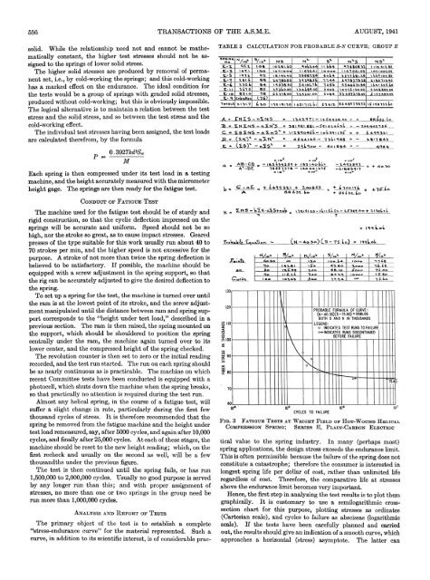
F i q . 3 F a t i g u e T e s t s a t W r i g h t F i e l d o f H o t - W o u n d H e l ic a l<br />
C o m p r e s s i o n S p r i n g ; S e r i e s E , P l a i n - C a r b o n E l e c t r ic<br />
tical value to the spring industry. In many (perhaps most)<br />
spring applications, the design stress exceeds the endurance limit.<br />
This is often permissible because the failure of the spring does not<br />
constitute a catastrophe; therefore the consumer is interested in<br />
longest spring life per dollar of cost, rather than unlimited life<br />
regardless of cost. Therefore, the comparative life at stresses<br />
above the endurance limit becomes very important.<br />
Hence, the first step in analyzing the test results is to plot them<br />
graphically. I t is customary to use a semilogarithmic crosssection<br />
chart for this purpose, plotting stresses as ordinates<br />
(Cartesian scale), and cycles to failure as abscissas (logarithmic<br />
scale). If the tests have been carefully planned and carried<br />
out, the results should give an indication of a smooth curve, which<br />
approaches a horizontal (stress) asymptote. The latter can


