

Transactions
Transactions
Transactions

Create successful ePaper yourself
Turn your PDF publications into a flip-book with our unique Google optimized e-Paper software.
BOYER, KUIVINEN—STRESS AND DEFLECTION IN RECIPROCATING PARTS OF ENGINES 503<br />
in tension the force due to reciprocating inertia plus the centrifugal<br />
force of the rotating end of the connecting rod (less that<br />
caused by the connecting-rod cap). In other types of engines,<br />
particularly double-acting engines, the actual maximum load<br />
must be determined by a complete analysis of loads for the<br />
entire cycle. The proportion of rotating and reciprocating<br />
portions of the rod can be determined by calculating its center of<br />
gravity or by weighing simultaneously the assembly on two scales.<br />
Crank-bearing bolts are very vital parts of an engine and<br />
failure may cause considerable damage to the balance of the<br />
engine. For this reason, stresses must be conservative and the<br />
material should be the best steel that is obtainable. A factor<br />
of safety of approximately 12 to 13, based on the ultimate strength<br />
of the steel, is recommended in selecting the bolt size for a known<br />
working load. Heat-treated chrome-molybdenum steels of excellent<br />
physical properties, both in ultimate tensile strength and<br />
impact resistance, can be obtained. On assembly, these bolts<br />
should be tightened to give an initial stress of approximately<br />
twice the actual working stress.<br />
It has been suggested that an important part of an engine,<br />
such as a crank-bearing bolt, should be replaced with a new one<br />
after a certain period of service because the bolt “fatigues” and<br />
must be replaced or it will ultimately fail. This should not be<br />
necessary if the engine is so designed that these bolts are not<br />
stressed to the endurance limit of the steel being used. Physical<br />
research on steels has proved that, when repeated stresses, below<br />
the static ultimate strength of the steel, are applied, failure<br />
occurs after a certain number of cycles. However, as various<br />
stresses are applied, there is a stress value below which the repeated<br />
loads can be applied with an indefinite number of cycles<br />
without failure. Research laboratories have accepted 10,000,000<br />
cycles as the point of measurement of the endurance limit.<br />
Therefore, if the stress is at such a value that the specimen will<br />
absorb 10,000,000 or more cycles without failure, it will go on<br />
indefinitely without failure at this stress. As long as the actual<br />
stresses used on the bolt are safely below this value, known as the<br />
“endurance limit,” these stresses therefore could be repeated<br />
indefinitely without failure. The fallacy of the practice of<br />
changing bolts every few years is apparent when considering<br />
that it would be necessary to change them perhaps each week or<br />
each month, depending upon engine speed, in order not to exceed<br />
10,000,000 cycles.<br />
C o n n e c t in g - R o d -B e a r i n g C a p s<br />
Regardless of the shape proposed for the cross section of the<br />
connecting-rod-bearing cap, the cap stress should be determined<br />
by the most severe consideration in order to gain rigidity.<br />
Again, it is not practical to state what definite deflections should<br />
be permitted, because the ideal would be zero and the limiting<br />
value is determined by good performance experience. The<br />
simplest method of gaining rigidity is to consider the cap as a<br />
freely supported curved beam. The supports are at the crankbearing-bolt<br />
center lines and the maximum load applied to the<br />
center of the cap as a concentrated load. The actual total load in<br />
all crank-bearing bolts, obtained from a study of the forces<br />
(inertia forces and others), can be this concentrated load. Again,<br />
I-beam cross sections give the most strength and rigidity with<br />
the least weight.<br />
The bending moment on the beam is the simple beam formula<br />
where M = moment, in-lb; P = load on cap, lb; and X = distance<br />
from nearest bolt to cross section under consideration, in.<br />
The stress caused by moment M in Equation [7] is determined<br />
by using the straight beam-stress formulas and applying a correction<br />
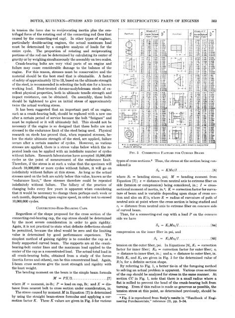
factor K. These K values are given in Fig. 5 for various<br />
types of cross sections.6 Thus, the stress at the section being considered<br />
is<br />
where Sb = bending stress, psi; M = bending moment from<br />
Equation [7]; c = distance from neutral axis to extreme fiber on<br />
side (tension or compression) being considered, in.; I = crosssectional<br />
moment of inertia, in.4; K = correction factor for curvature<br />
of beam and is variable depending upon shape of cross section<br />
and also on jR/ci where R = radius of curvature of path of<br />
neutral axis at point where the cross section is being studied and<br />
ci = distance from neutral axis to extreme fiber on concave side<br />
of curved beam.<br />
Thus, for a connecting-rod cap with a load P on the concave<br />
side we have<br />
compression on the inner fiber in psi, and<br />
tension on the outer fiber, psi. In Equations [8], Ki = correction<br />
factor for inner fiber; K 2 = correction factor for outer fiber; ci<br />
= distance to inner fiber, in.; and c2 = distance to outer fiber, in.<br />
Both Ki and K2 are given in Fig. 5 for the determined value of<br />
R/ci for a definite section shape.<br />
By referring to Fig. 1, a better tie-in of the foregoing method<br />
to solving an actual problem is apparent. Various cross sections<br />
of the cap should be analyzed for stress in the same manner. At<br />
section CC in Fig. 1, note that there is a small radius where a<br />
flat is milled to prevent the head of the crank-bearing bolt from<br />
turning. Even if this radius is made as generous as possible, the<br />
tension stress at this point, as determined previously, should be<br />
6 Fig. 5 is reproduced from Seely’s results in “Handbook of Engineering<br />
Fundamentals,” reference (3), pp. 5-34.


