LOGIC DESIGN LABORATORY MANUAL - VTU e-Learning Centre
LOGIC DESIGN LABORATORY MANUAL - VTU e-Learning Centre
LOGIC DESIGN LABORATORY MANUAL - VTU e-Learning Centre

Create successful ePaper yourself
Turn your PDF publications into a flip-book with our unique Google optimized e-Paper software.
Logic Design Laboratory Manual 12<br />
___________________________________________________________________________<br />
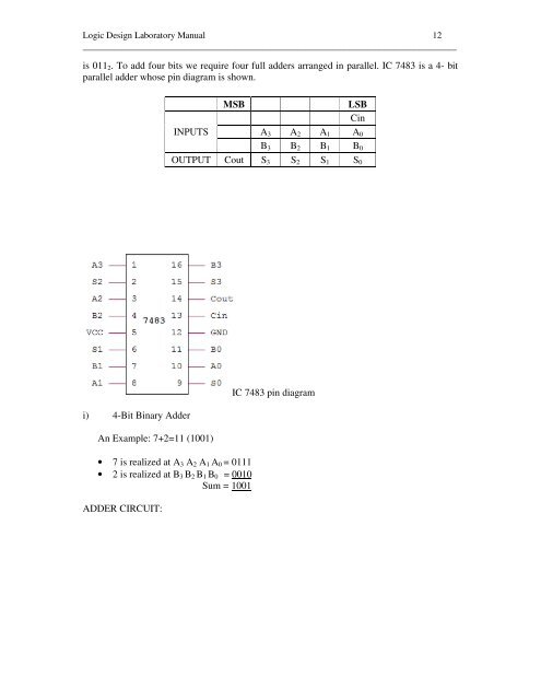
is 011 2 . To add four bits we require four full adders arranged in parallel. IC 7483 is a 4- bit<br />
parallel adder whose pin diagram is shown.<br />
INPUTS<br />
MSB<br />
LSB<br />
Cin<br />
A 3 A 2 A 1 A 0<br />
B 3 B 2 B 1 B 0<br />
OUTPUT Cout S 3 S 2 S 1 S 0<br />
i) 4-Bit Binary Adder<br />
An Example: 7+2=11 (1001)<br />
• 7 is realized at A 3 A 2 A 1 A 0 = 0111<br />
• 2 is realized at B 3 B 2 B 1 B 0 = 0010<br />
Sum = 1001<br />
ADDER CIRCUIT:<br />
IC 7483 pin diagram