LOGIC DESIGN LABORATORY MANUAL - VTU e-Learning Centre
LOGIC DESIGN LABORATORY MANUAL - VTU e-Learning Centre
LOGIC DESIGN LABORATORY MANUAL - VTU e-Learning Centre

Create successful ePaper yourself
Turn your PDF publications into a flip-book with our unique Google optimized e-Paper software.
Logic Design Laboratory Manual 30<br />
___________________________________________________________________________<br />
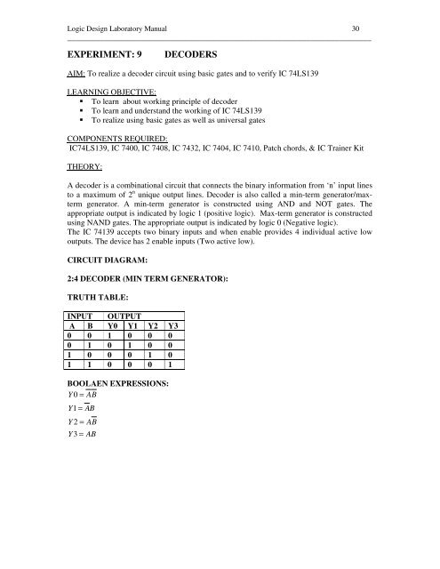
EXPERIMENT: 9<br />
DECODERS<br />
AIM: To realize a decoder circuit using basic gates and to verify IC 74LS139<br />
LEARNING OBJECTIVE:<br />
To learn about working principle of decoder<br />
To learn and understand the working of IC 74LS139<br />
To realize using basic gates as well as universal gates<br />
COMPONENTS REQUIRED:<br />
IC74LS139, IC 7400, IC 7408, IC 7432, IC 7404, IC 7410, Patch chords, & IC Trainer Kit<br />
THEORY:<br />
A decoder is a combinational circuit that connects the binary information from ‘n’ input lines<br />
to a maximum of 2 n unique output lines. Decoder is also called a min-term generator/maxterm<br />
generator. A min-term generator is constructed using AND and NOT gates. The<br />
appropriate output is indicated by logic 1 (positive logic). Max-term generator is constructed<br />
using NAND gates. The appropriate output is indicated by logic 0 (Negative logic).<br />
The IC 74139 accepts two binary inputs and when enable provides 4 individual active low<br />
outputs. The device has 2 enable inputs (Two active low).<br />
CIRCUIT DIAGRAM:<br />
2:4 DECODER (MIN TERM GENERATOR):<br />
TRUTH TABLE:<br />
INPUT OUTPUT<br />
A B Y0 Y1 Y2 Y3<br />
0 0 1 0 0 0<br />
0 1 0 1 0 0<br />
1 0 0 0 1 0<br />
1 1 0 0 0 1<br />
BOOLAEN EXPRESSIONS:<br />
Y 0 = AB<br />
Y1<br />
= AB<br />
Y 2 = AB<br />
Y3<br />
= AB