LOGIC DESIGN LABORATORY MANUAL - VTU e-Learning Centre
LOGIC DESIGN LABORATORY MANUAL - VTU e-Learning Centre
LOGIC DESIGN LABORATORY MANUAL - VTU e-Learning Centre

You also want an ePaper? Increase the reach of your titles
YUMPU automatically turns print PDFs into web optimized ePapers that Google loves.
Logic Design Laboratory Manual 46<br />
___________________________________________________________________________<br />
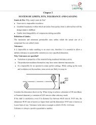
EXPERIMENT: 14<br />
SEQUENCE GENERATOR<br />
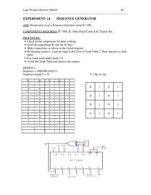
AIM: Design and set up a Sequence Generator using IC 7495.<br />
COMPONENTS REQUIRED: IC 7495, IC 7486, Patch Cords & IC Trainer Kit.<br />
PROCEDURE:<br />
• Check all the components for their working.<br />
• Insert the appropriate IC into the IC base.<br />
• Make connections as shown in the circuit diagram.<br />
• By Keeping mode=1. Load the input A,B,C,D as in Truth Table 1 st Row and give a clock<br />
pulse<br />
• For count mode make mode = 0.<br />
• Verify the Truth Table and observe the outputs.<br />
<strong>DESIGN</strong> 1:<br />
Sequence = 100010011010111<br />
Sequence length S = 15<br />
Q A Q B Q C Q D Y<br />
1 1 1 1 0<br />
0 1 1 1 0<br />
0 0 1 1 0<br />
0 0 0 1 1<br />
1 0 0 0 0<br />
0 1 0 0 0<br />
0 0 1 0 1<br />
1 0 0 1 1<br />
1 1 0 0 0<br />
0 1 1 0 1<br />
1 0 1 1 0<br />
0 1 0 1 1<br />
1 0 1 0 1<br />
1 1 0 1 1<br />
1 1 1 0 1<br />
1 1 1<br />
1 1<br />
1<br />
Y = Q C (+) Q D<br />
X 1 0 1<br />
0 1 0 1<br />
0 1 0 1<br />
0 1 0 1<br />
Y<br />
VCC<br />
QA<br />
QB<br />
3<br />
2<br />
1<br />
QC QD<br />
CLK<br />
14<br />
13<br />
12<br />
11<br />
10 9<br />
8<br />
IC 7495<br />
1<br />
2<br />
3 4 5<br />
6<br />
7<br />
Serial<br />
Input<br />
A<br />
B<br />
INPUTS<br />
C<br />
D<br />
Mode<br />
Control<br />
Gnd