LOGIC DESIGN LABORATORY MANUAL - VTU e-Learning Centre
LOGIC DESIGN LABORATORY MANUAL - VTU e-Learning Centre
LOGIC DESIGN LABORATORY MANUAL - VTU e-Learning Centre

Create successful ePaper yourself
Turn your PDF publications into a flip-book with our unique Google optimized e-Paper software.
Logic Design Laboratory Manual 13<br />
___________________________________________________________________________<br />
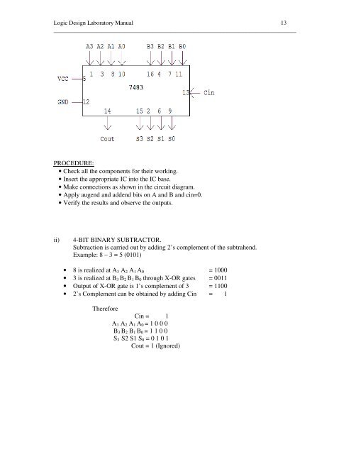
PROCEDURE:<br />
• Check all the components for their working.<br />
• Insert the appropriate IC into the IC base.<br />
• Make connections as shown in the circuit diagram.<br />
• Apply augend and addend bits on A and B and cin=0.<br />
• Verify the results and observe the outputs.<br />
ii)<br />
4-BIT BINARY SUBTRACTOR.<br />
Subtraction is carried out by adding 2’s complement of the subtrahend.<br />
Example: 8 – 3 = 5 (0101)<br />
• 8 is realized at A 3 A 2 A 1 A 0 = 1000<br />
• 3 is realized at B 3 B 2 B 1 B 0 through X-OR gates = 0011<br />
• Output of X-OR gate is 1’s complement of 3 = 1100<br />
• 2’s Complement can be obtained by adding Cin = 1<br />
Therefore<br />
Cin = 1<br />
A 3 A 2 A 1 A 0 = 1 0 0 0<br />
B 3 B 2 B 1 B 0 = 1 1 0 0<br />
S 3 S2 S1 S 0 = 0 1 0 1<br />
Cout = 1 (Ignored)