LOGIC DESIGN LABORATORY MANUAL - VTU e-Learning Centre
LOGIC DESIGN LABORATORY MANUAL - VTU e-Learning Centre
LOGIC DESIGN LABORATORY MANUAL - VTU e-Learning Centre
Create successful ePaper yourself
Turn your PDF publications into a flip-book with our unique Google optimized e-Paper software.
Logic Design Laboratory Manual 1<br />
___________________________________________________________________________<br />
EXPERIMENT: 1<br />
<strong>LOGIC</strong> GATES<br />
AIM: To study and verify the truth table of logic gates<br />
LEARNING OBJECTIVE:<br />
• Identify various ICs and their specification.<br />
COMPONENTS REQUIRED:<br />
• Logic gates (IC) trainer kit.<br />
• Connecting patch chords.<br />
• IC 7400, IC 7408, IC 7432, IC 7406, IC 7402, IC 7404, IC 7486<br />
THEORY:<br />
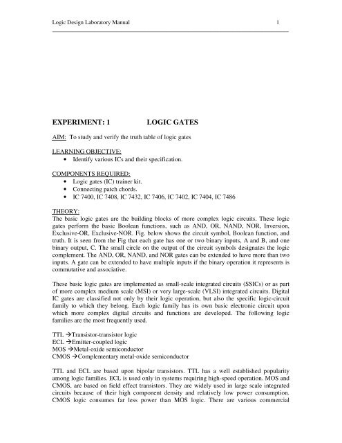
The basic logic gates are the building blocks of more complex logic circuits. These logic<br />
gates perform the basic Boolean functions, such as AND, OR, NAND, NOR, Inversion,<br />
Exclusive-OR, Exclusive-NOR. Fig. below shows the circuit symbol, Boolean function, and<br />
truth. It is seen from the Fig that each gate has one or two binary inputs, A and B, and one<br />
binary output, C. The small circle on the output of the circuit symbols designates the logic<br />
complement. The AND, OR, NAND, and NOR gates can be extended to have more than two<br />
inputs. A gate can be extended to have multiple inputs if the binary operation it represents is<br />
commutative and associative.<br />
These basic logic gates are implemented as small-scale integrated circuits (SSICs) or as part<br />
of more complex medium scale (MSI) or very large-scale (VLSI) integrated circuits. Digital<br />
IC gates are classified not only by their logic operation, but also the specific logic-circuit<br />
family to which they belong. Each logic family has its own basic electronic circuit upon<br />
which more complex digital circuits and functions are developed. The following logic<br />
families are the most frequently used.<br />
TTL Transistor-transistor logic<br />
ECL Emitter-coupled logic<br />
MOS Metal-oxide semiconductor<br />
CMOS Complementary metal-oxide semiconductor<br />
TTL and ECL are based upon bipolar transistors. TTL has a well established popularity<br />
among logic families. ECL is used only in systems requiring high-speed operation. MOS and<br />
CMOS, are based on field effect transistors. They are widely used in large scale integrated<br />
circuits because of their high component density and relatively low power consumption.<br />
CMOS logic consumes far less power than MOS logic. There are various commercial


