LOGIC DESIGN LABORATORY MANUAL - VTU e-Learning Centre
LOGIC DESIGN LABORATORY MANUAL - VTU e-Learning Centre
LOGIC DESIGN LABORATORY MANUAL - VTU e-Learning Centre

Create successful ePaper yourself
Turn your PDF publications into a flip-book with our unique Google optimized e-Paper software.
Logic Design Laboratory Manual 49<br />
___________________________________________________________________________<br />
EXPERIMENT: 15<br />
RING COUNTER AND JOHNSON COUNTER<br />
AIM: To realize and study Ring Counter and Johnson counter.<br />
LEARNING OBJECTIVE:<br />
To learn about Ring Counter and its application<br />
To learn about Johnson Counter and its application<br />
COMPONENTS REQUIRED:<br />
IC 7495, IC 7404, Patch Cords & IC Trainer Kit.<br />
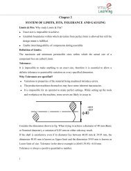
THEORY:<br />
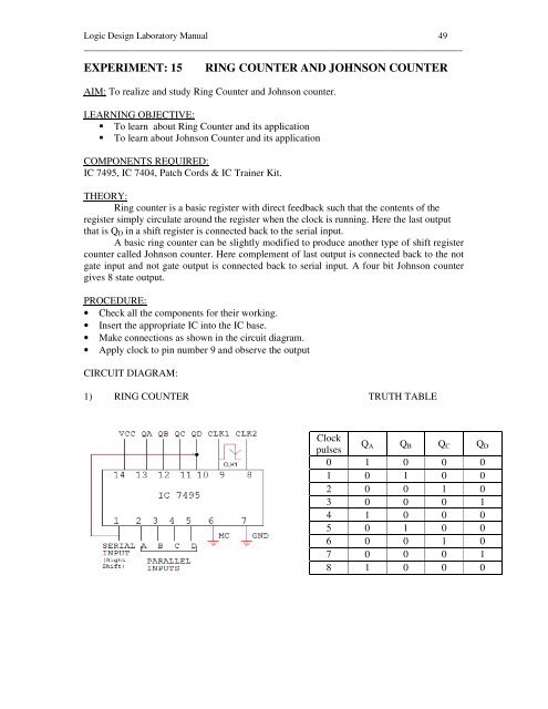
Ring counter is a basic register with direct feedback such that the contents of the<br />
register simply circulate around the register when the clock is running. Here the last output<br />
that is Q D in a shift register is connected back to the serial input.<br />
A basic ring counter can be slightly modified to produce another type of shift register<br />
counter called Johnson counter. Here complement of last output is connected back to the not<br />
gate input and not gate output is connected back to serial input. A four bit Johnson counter<br />
gives 8 state output.<br />
PROCEDURE:<br />
• Check all the components for their working.<br />
• Insert the appropriate IC into the IC base.<br />
• Make connections as shown in the circuit diagram.<br />
• Apply clock to pin number 9 and observe the output<br />
CIRCUIT DIAGRAM:<br />
1) RING COUNTER TRUTH TABLE<br />
Clock<br />
pulses<br />
Q A Q B Q C Q D<br />
0 1 0 0 0<br />
1 0 1 0 0<br />
2 0 0 1 0<br />
3 0 0 0 1<br />
4 1 0 0 0<br />
5 0 1 0 0<br />
6 0 0 1 0<br />
7 0 0 0 1<br />
8 1 0 0 0