LOGIC DESIGN LABORATORY MANUAL - VTU e-Learning Centre
LOGIC DESIGN LABORATORY MANUAL - VTU e-Learning Centre
LOGIC DESIGN LABORATORY MANUAL - VTU e-Learning Centre

You also want an ePaper? Increase the reach of your titles
YUMPU automatically turns print PDFs into web optimized ePapers that Google loves.
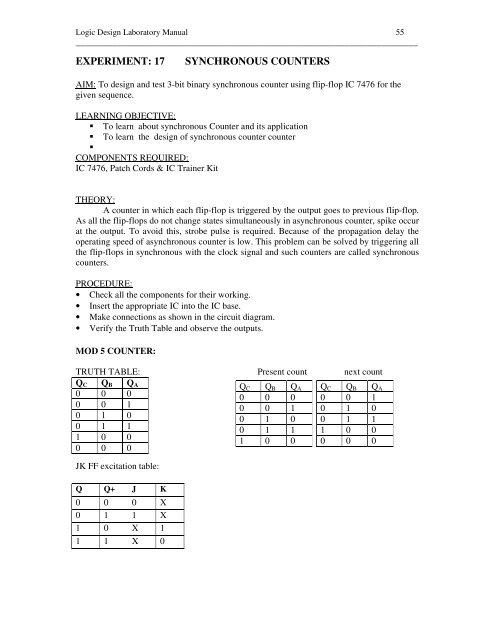
Logic Design Laboratory Manual 55<br />
___________________________________________________________________________<br />
EXPERIMENT: 17<br />
SYNCHRONOUS COUNTERS<br />
AIM: To design and test 3-bit binary synchronous counter using flip-flop IC 7476 for the<br />
given sequence.<br />
LEARNING OBJECTIVE:<br />
To learn about synchronous Counter and its application<br />
To learn the design of synchronous counter counter<br />
<br />
COMPONENTS REQUIRED:<br />
IC 7476, Patch Cords & IC Trainer Kit<br />
THEORY:<br />
A counter in which each flip-flop is triggered by the output goes to previous flip-flop.<br />
As all the flip-flops do not change states simultaneously in asynchronous counter, spike occur<br />
at the output. To avoid this, strobe pulse is required. Because of the propagation delay the<br />
operating speed of asynchronous counter is low. This problem can be solved by triggering all<br />
the flip-flops in synchronous with the clock signal and such counters are called synchronous<br />
counters.<br />
PROCEDURE:<br />
• Check all the components for their working.<br />
• Insert the appropriate IC into the IC base.<br />
• Make connections as shown in the circuit diagram.<br />
• Verify the Truth Table and observe the outputs.<br />
MOD 5 COUNTER:<br />
TRUTH TABLE: Present count next count<br />
Q C Q B Q A<br />
Q C Q B Q A Q C Q B Q A<br />
0 0 0<br />
0 0 0 0 0 1<br />
0 0 1<br />
0 0 1 0 1 0<br />
0 1 0<br />
0 1 0 0 1 1<br />
0 1 1<br />
0 1 1 1 0 0<br />
1 0 0<br />
1 0 0 0 0 0<br />
0 0 0<br />
JK FF excitation table:<br />
Q Q+ J K<br />
0 0 0 X<br />
0 1 1 X<br />
1 0 X 1<br />
1 1 X 0