

Kop-Flex Industrial Coupling Product Catalog - Form 8887E
Kop-Flex Industrial Coupling Product Catalog - Form 8887E
Kop-Flex Industrial Coupling Product Catalog - Form 8887E

Create successful ePaper yourself
Turn your PDF publications into a flip-book with our unique Google optimized e-Paper software.
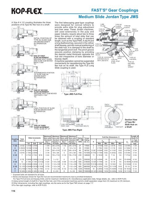
Fast’s ® Gear <strong>Coupling</strong>s<br />
Medium Slide Jordan Type JMS<br />
A Size # 4 1/2 coupling illustrates the three<br />
positions of its Type MJ flex hub on a shaft:<br />
INITIAL POSITION OF<br />
TYPE MJ SLIDE HUB<br />
ON DRIVEN SHAFT<br />
IN OPERATION<br />
TO<br />
END OF FIRST<br />
SLIDE INCREMENT<br />
MACHINE SHUT DOWN<br />
AND SLIDE HUB MOVED<br />
BACK 4 1/64"<br />
TO<br />
The first telescoping gear-type couplings<br />
were designed for conical refiners to<br />
provide extra slide for plug adjustment<br />
and liner wear. These Jordan machines,<br />
still used extensively in the pulp and<br />
paper industry, require about two to three<br />
times the amount of total slide that can<br />
be obtained with a coupling of standard<br />
length, such as the Type FMS. A slip fit and<br />
a long feathered key, secured in the refiner<br />
shaft keyway, permits manual positioning of<br />
the slide hub. It is clamped to the shaft by<br />
the tangential pinch-bolt. The pinch groove<br />
assures positive clamping by providing<br />
the desired metal thickness opposite the<br />
hub slot irrespective of bore diameter or<br />
keyway depth.<br />
If machine operation cannot be suspended<br />
momentarily for repositioning the Type MJ<br />
flex hub on its shaft, the Type FLS Long<br />
Slide coupling is used.<br />
TYPE FS<br />
FLEX HUB<br />
LUBE<br />
PLUGS<br />
TYPE FM<br />
SLEEVE<br />
LUBE PASSAGE<br />
HOLES<br />
TYPE JM<br />
EXPOSED BOLTS<br />
WITH JAM NUTS<br />
TYPE FM<br />
FLANGE<br />
GASKETS<br />
THROUGH<br />
GEAR<br />
TYPE FM<br />
STEEL STOP<br />
PLATE<br />
TYPE MS<br />
SLEEVE<br />
PINCH<br />
TYPE MJ GROOVE<br />
FLEX HUB<br />
HUB<br />
SLOT<br />
TYPE MJ<br />
PINCH<br />
BOLT<br />
TYPE UD<br />
HUB SEAL<br />
TYPE UD<br />
END RING<br />
AND<br />
GASKET<br />
INTERMEDIATE POSITION<br />
OF SLIDE HUB ON<br />
DRIVEN SHAFT<br />
IN OPERATION<br />
TO<br />
END OF SECOND<br />
SLIDE INCREMENT<br />
MACHINE SHUT HUB MOVED<br />
ANOTHER 4 1/64"<br />
TO<br />
Type JMS Full-<strong>Flex</strong><br />
FINAL POSITION OF SLIDE<br />
HUB ON DRIVEN SHAFT<br />
IN OPERATION<br />
TO<br />
END OF THIRD<br />
SLIDE INCREMENT<br />
TOTAL SLIDE OF 12"<br />
Type JMS <strong>Flex</strong>-Rigid<br />
Section View<br />
of Type MJ<br />
Slide Hub on<br />
a Shaft<br />
Maximum Maximum Maximum Maximum<br />
Length of<br />
Full-<strong>Flex</strong> Dimensions 2<br />
Slide Increments Bore with Bore with Bore with Bore with Rating Torque<br />
Shaft Fit<br />
<strong>Coupling</strong> Total<br />
Standard Standard Standard Standard HP / 100 Rating<br />
in Type<br />
Size Slide1<br />
1<br />
C<br />
Key † Keyway † Key † Keyway † RPM (lb.-in.) A<br />
H<br />
C S EJ MJ Slide<br />
1st<br />
2nd<br />
3 rd<br />
FS Hubs FS Hubs MJ Hubs MJ Hubs<br />
M ax.<br />
M in.<br />
M ax.<br />
Min.<br />
Hub<br />
1 1/2 3 5/32<br />
1 37/64<br />
1 37/64<br />
- 1 5/ 8 3/8<br />
x 3/16<br />
1 1/ 2 3/8<br />
x 3/16<br />
27<br />
17000<br />
6 1 47/64<br />
5/32<br />
3 5/16<br />
5/32<br />
3 21/64<br />
1 3/ 4<br />
2 3 29/32<br />
1 61/64<br />
1 61/64<br />
- 2 1/ 8 1/2<br />
x 1/ 4 2 1/2<br />
x 1/ 4 50<br />
31500<br />
7 2 7/64<br />
5/32<br />
4 1/16<br />
5/32<br />
4 13/64<br />
2 1/ 4<br />
2 1/2 4 3/16<br />
2 33/64<br />
1 43/64<br />
- 2 3/ 4 5/8<br />
x 5/16<br />
2 1/ 2 5/8<br />
x 5/16<br />
90<br />
56700<br />
8 3/ 8 2 43/64<br />
5/32<br />
4 11/32<br />
5/32<br />
4 27/64<br />
2 3/ 4<br />
3 5 9/16<br />
3 1/64<br />
2 35/64<br />
- 3 1/ 8 3/4<br />
x 3/ 8 3 3/4<br />
x 3/ 8 160<br />
101000<br />
9 7/16<br />
3 11/64<br />
5/32<br />
5 23/32<br />
5/32<br />
5 51/64<br />
3 1/ 4<br />
3 1/2 7 3 7/32<br />
3 7/32<br />
9/16<br />
3 3/ 4 7/8<br />
x 7/16<br />
3 1/ 2 7/8<br />
x 7/16<br />
235<br />
148000<br />
11<br />
3 15/32<br />
1/<br />
4 7 1/ 4 1/<br />
4 7 17/32<br />
3 3/ 4<br />
4 9 7/ 8 3 29/64<br />
3 29/64<br />
2 31/32<br />
4 1/ 4 1 x 1/ 2 4 1 x 1/ 2 375<br />
236000<br />
12<br />
1/ 2 3 45/64<br />
1/<br />
4 10<br />
1/ 8 1/<br />
4 10<br />
43/64<br />
4 1/ 4<br />
4 1/2 12<br />
4 1/64<br />
4 1/64<br />
3 31/32<br />
4 3/ 4 1 1/4 x 5/ 8 4 5/ 8 1 1/4 x 5/ 8 505<br />
318000<br />
13<br />
5/ 8 4 17/64<br />
1/<br />
4 12<br />
1/ 4 1/<br />
4 12<br />
45/64<br />
4 23/32<br />
5 12<br />
1/32<br />
4 29/64<br />
4 29/64<br />
3 1/ 8 5 1/ 2 1 1/4 x 5/ 8 5 1/ 4 1 1/4 x 5/ 8 700<br />
441000<br />
15<br />
5/16<br />
4 45/64<br />
1/<br />
4 12<br />
9/32<br />
1/<br />
4 12<br />
53/64<br />
5 1/ 4<br />
5 1/2 12<br />
1/32<br />
4 25/64<br />
4 25/32<br />
2 15/32<br />
5 7/ 8 1 1/2 x 3/ 4 6 1 1/2 x 3/ 4 920<br />
580000<br />
16<br />
3/ 4 5 3/32<br />
5/16<br />
12<br />
11/32<br />
5/16<br />
12<br />
1/ 2 5 1/ 4<br />
6 15<br />
21/64<br />
5 7/64<br />
5 7/64<br />
5 7/64<br />
6 1/ 2 1 1/2 x 3/ 4 6 1/ 2 1 1/2 x 3/ 4 1205<br />
759000<br />
18<br />
5 29/64<br />
11/32<br />
15<br />
43/64<br />
11/32<br />
16<br />
15/32<br />
6 1/ 4<br />
7 18<br />
9/64<br />
6 3/64<br />
6 3/64<br />
6 3/64<br />
8 2 x 3/ 4 8 2 x 3/ 4 1840<br />
1160000<br />
20<br />
3/ 4 6 29/64<br />
13/32<br />
18<br />
35/64<br />
13/32<br />
19<br />
11/32<br />
7 1/ 4<br />
* Exposed bolts are standard for all sizes.<br />
† Bores and keyways shown for Type MJ hub are recommended maximums due to pinchbolt limitations.<br />
For Type FS hub bore and keyway limits, and for maximum interference fit, miscellaneous application data, flange details, etc., refer to KOP-FLEX.<br />
¬ Using correct length of shaft fit in Type MJ flex hub, and if the connected machines permit a shaft separation range from CS maximum to CS minimum.<br />
Other dimensions, including flex-rigid couplings, are the same as for the Type FMS shown on page 117<br />
® For flex-rigid couplings, refer to KOP-FLEX.<br />
116


