

Kop-Flex Industrial Coupling Product Catalog - Form 8887E
Kop-Flex Industrial Coupling Product Catalog - Form 8887E
Kop-Flex Industrial Coupling Product Catalog - Form 8887E

You also want an ePaper? Increase the reach of your titles
YUMPU automatically turns print PDFs into web optimized ePapers that Google loves.
1. Select <strong>Coupling</strong> Based on Bore Capacity.<br />
Select the coupling size that has a maximum bore<br />
capacity equal to or larger than the larger of the<br />
two shafts. For interference fits larger than AGMA<br />
standards, consult <strong>Kop</strong>-<strong>Flex</strong>.<br />
2. Verify <strong>Coupling</strong> Size Based on Load Rating.<br />
a. Select appropriate Service Factor from the Table on<br />
page 128.<br />
b. Calculate required HP / 100 RPM:<br />
HP x Service Factor x 100<br />
= HP / 100 RPM<br />
RPM<br />
c. Verify that the selected coupling has a rating<br />
greater than or equal to the required HP / 100<br />
RPM.<br />
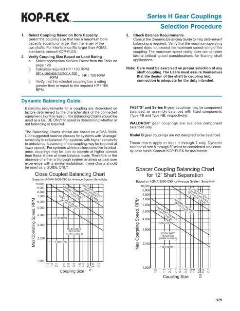
Dynamic Balancing Guide<br />
Balancing requirements for a coupling are dependent on<br />
factors determined by the characteristics of the connected<br />
equipment. For this reason, the Balancing Charts should be<br />
used as a GUIDE ONLY to assist in determining whether or<br />
not balancing is required.<br />
The Balancing Charts shown are based on AGMA 9000-<br />
C90 suggested balance classes for systems with “Average”<br />
sensitivity to unbalance. For systems with higher sensitivity<br />
to unbalance, balancing of the coupling may be required at<br />
lower speeds. For systems which are less sensitive to unbalance,<br />
couplings may be able to operate at higher speeds<br />
than those shown at lower balance levels. Therefore, in the<br />
absence of either a thorough system analysis or past user<br />
experience with a similar installation, these charts should<br />
be used as a GUIDE ONLY.<br />
Series H Gear <strong>Coupling</strong>s<br />
Selection Procedure<br />
3. Check Balance Requirements.<br />
Consult the Dynamic Balancing Guide to help determine if<br />
balancing is required. Verify that the maximum operating<br />
speed does not exceed the maximum speed rating of the<br />
coupling. The maximum speed rating does not consider<br />
lateral critical speed considerations for floating shaft<br />
applications.<br />
Note: Care must be exercised on proper selection of any<br />
shaft coupling. The Users must assure themselves<br />
that the design of the shaft to coupling hub<br />
connection is adequate for the duty intended.<br />
Fast’s ® and Series H gear couplings may be component<br />
balanced, or assembly balanced with fitted components<br />
(Type FB and Type HB, respectively).<br />
Waldron ® gear couplings are available component<br />
balanced only.<br />
Model B gear couplings are not designed to be balanced.<br />
These charts apply to sizes 1 through 7 only. Dynamic<br />
balance of size 8 through 30 must be considered on a caseby-case<br />
basis. Consult <strong>Kop</strong>-<strong>Flex</strong> for assistance.<br />
129


