Kop-Flex Industrial Coupling Product Catalog - Form 8887E
Kop-Flex Industrial Coupling Product Catalog - Form 8887E
Kop-Flex Industrial Coupling Product Catalog - Form 8887E
You also want an ePaper? Increase the reach of your titles
YUMPU automatically turns print PDFs into web optimized ePapers that Google loves.
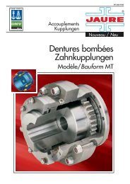
The barrel coupling consists of a sleeve<br />
provided with semicircular toothing around its<br />
internal diameter and a hub that is externally<br />
toothed in a similar way. A series of cylindrical<br />
barrels, of hardened steel, are inserted in the<br />
holes formed by this toothing to act as power<br />
transmission elements.<br />
Covers with their corresponding special seals<br />
serve to assure the perfect tightness of the<br />
inner zone, preventing the penetration of<br />
dust and guaranteeing the continuity of the<br />
necessary lubrication. Two double-lamina<br />
elastic rings mounted on the hub, one on each<br />
side of the toothing, limit the axial displacement<br />
of the barrels.<br />
The convex shape of the barrels and the<br />
internal spaces of the toothing allows the<br />
oscillation of the hub relative to the sleeve,<br />
compensating angular misalignments of ±<br />
1º 30’ and an axial displacement that varies<br />
between ± 3 mm and ± 8 mm (see Table 5,<br />
page 270).<br />
Torque is transmitted to the drum’s receiving<br />
flange, generally by two diametrically opposed<br />
flat driving surfaces, located at the periphery<br />
of the coupling flange, and also by means of a<br />
series of bolts which, at the same time, serve<br />
as connection with the drum.<br />
Barrel <strong>Coupling</strong>s<br />
Description and Characteristics<br />
Other connection systems, such as adjusted<br />
spring pins or similar, can also be used following<br />
the adequate preparation of the flanges (see<br />
TCB with special flange on page 274).<br />
The described design is appropriate for bearing<br />
large radial loads, as these are distributed over<br />
large barrel support surfaces. In the same<br />
way, this design also minimises the effect<br />
of alternative bending of the torque on the<br />
toothing, the latter being robust thanks to its<br />
low height and large bottom section. In addition<br />
to this, due to the effect of a “crush polishing”<br />
of the hardened barrel on the tooth profile, its<br />
wear resistance is appreciably improved.<br />
An indicator located on the outer cover (Pos.<br />
10, Fig. 4), which moves relative to the marks<br />
provided on the hub as a function of wear,<br />
permits control of internal wear of the toothing<br />
without the need to disassemble any part of<br />
the coupling. The same indicator also serves to<br />
control the axial position of the sleeve relative to<br />
the hub. Optionally, an electronic wear indicator<br />
can be installed for remote control (for more<br />
details see page 275).<br />
262


