

Kop-Flex Industrial Coupling Product Catalog - Form 8887E
Kop-Flex Industrial Coupling Product Catalog - Form 8887E
Kop-Flex Industrial Coupling Product Catalog - Form 8887E

Create successful ePaper yourself
Turn your PDF publications into a flip-book with our unique Google optimized e-Paper software.
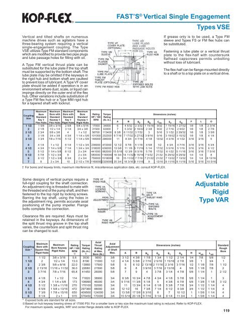
Fast’s ® Vertical Single Engagement<br />
Types VSE<br />
Vertical and tilted shafts on numerous<br />
machine drives such as agitators have a<br />
three-bearing system requiring a vertical<br />
single-engagement coupling. The Type<br />
VSE utilizes Type FM standard components<br />
which are modified to provide two pipe plugs<br />
and lube passage holes for filling with oil.<br />
A Type FM vertical thrust plate can be<br />
substituted for the lube plate if the top shaft<br />
must be supported by the bottom shaft. The<br />
lube plate may be omitted if the keyways in<br />
the rigid hub and bottom shaft are caulked<br />
to prevent loss of lubricant. A Type VF cover<br />
plate should be added if operation is in an<br />
environment where dust, scale, or liquid can<br />
impinge directly on the outer end of the flex<br />
hub. Other variations include substitution of<br />
a Type FM flex hub or a Type MM rigid hub<br />
for a tapered shaft with locknut.<br />
If grease only is to be used, a Type FM<br />
sleeve and Types FS or FM flex hubs can<br />
be substituted.<br />
Fastening a lube plate or a vertical thrust<br />
plate to the flex-half with countersunk<br />
flathead capscrews permits unbolting<br />
without loss of lubricant.<br />
The flex-half can be flange-mounted directly<br />
to a shaft or to a top plate on a vertical drive.<br />
<strong>Coupling</strong><br />
Size<br />
Maximum<br />
Bore<br />
Standard<br />
Key †<br />
<strong>Flex</strong> Hubs<br />
Maximum<br />
Bore with<br />
Standard<br />
Keyway †<br />
<strong>Flex</strong> Hubs<br />
Maximum<br />
Bore with<br />
Standard<br />
Key †<br />
Rigid Hubs<br />
1 5/ 3/8<br />
x 3/16<br />
5/ 8<br />
2 1/ 1/2<br />
x 1/ 4 1/ 4<br />
2 3/ /8 x 3/ 8<br />
3 1/ 3/4<br />
x 3/ 8 3/ 4<br />
3 3/ 7/8<br />
x 7/16<br />
1/ 2<br />
1 1/2 8<br />
2 8<br />
2 1/2 4<br />
3 8<br />
3 1/2 4<br />
Maximum<br />
Bore Rating<br />
Standard HP / 100<br />
Keyway † RPM<br />
Rigid Hubs<br />
5/8<br />
x 5/1 7000<br />
3/4<br />
x 3/ 1500<br />
1 x 1/ 6700<br />
1 1/4 x 5/ 01000<br />
1 1/4 x 5/ 48000<br />
2 6<br />
3 8<br />
5 4 2<br />
4 8<br />
5 8<br />
† For bores and keyway limits, maximum interference fit, miscellaneous application data, etc. consult KOP-FLEX.<br />
Some designs of vertical pumps require a<br />
full-rigid coupling for the shaft connection.<br />
An adjustment ring is threaded to mate with<br />
the threaded end of the pump shaft, and then<br />
fastened to the top rigid by locking screws.<br />
Barring the top shaft, using the holes in<br />
the adjustment ring, permits accurate axial<br />
positioning of the pump impeller. Flange<br />
bolts complete the connection.<br />
Clearance fits are required. Keys must be<br />
retained in the keyways. As dimensions of<br />
the split thrust ring groove in the top shaft<br />
varies, the counterbore and split thrust ring<br />
can be changed to suit.<br />
Torque<br />
Rating<br />
(lb.-in.)<br />
Dimensions (inches)<br />
A B B F<br />
B R<br />
C FR<br />
E F<br />
E R<br />
F L O<br />
1 34000<br />
6 4 5/32<br />
2 3/32<br />
1 15/16<br />
9/32<br />
1 15/16<br />
1 27/32<br />
1/<br />
8 1/<br />
8 2 3/16<br />
3 63000<br />
7 5 3/32<br />
2 19/32<br />
2 3/ 8 9/32<br />
2 7/16<br />
2 9/32<br />
1/<br />
8 1/<br />
8 2 7/ 8<br />
5 113400<br />
8 3/ 8 6 11/32<br />
3 7/32<br />
3 5/16<br />
3 1/32<br />
2 29/32<br />
1/<br />
8 1/<br />
8 3 5/ 8<br />
1 202000<br />
9 7/16<br />
7 17/32<br />
3 27/32<br />
3 9/16<br />
5/16<br />
3 19/32<br />
3 15/32<br />
1/<br />
8 1/<br />
8 4 1/ 4<br />
1 296000<br />
11<br />
8 3/ 4 4 7/16<br />
4 1/ 8 13/32<br />
4 3/16<br />
4 1/32<br />
3/16<br />
3/16<br />
5<br />
4 4 1/ 4 1 x 1/ 2 6 1/ 4 1 1/2 x 3/ 4 236000<br />
472000<br />
12<br />
1/ 2 9 7/ 8 5 1/16<br />
4 5/ 8 1/<br />
2 4 3/ 4 4 7/16<br />
3/16<br />
3/16<br />
5 3/ 4<br />
4 1/2 4 3/ 4 1 1/4 x 5/ 8 7 1/ 4 1 3/4 x 3/ 4 318000<br />
636000<br />
13<br />
5/ 8 11<br />
1/ 8 5 11/16<br />
5 1/ 4 17/32<br />
5 5/16<br />
5 1/16<br />
3/16<br />
3/16<br />
6 1/ 2<br />
5 5 1/ 2 1 1/4 x 5/ 8 8 1/ 2 2 x 3/ 4 441000<br />
882000<br />
15<br />
5/16<br />
12<br />
3/ 8 6 5/16<br />
5 7/ 8 17/32<br />
6 1/32<br />
5 11/16<br />
3/16<br />
3/16<br />
7 5/16<br />
5 1/2 5 7/ 8 1 1/2 x 3/ 4 8 2 x 3/ 4 580000<br />
1160000<br />
16<br />
3/ 4 14<br />
11/326 15/16<br />
7 5/32<br />
21/32<br />
6 29/32<br />
6 29/32<br />
1/<br />
4 1/<br />
4 8<br />
6 6 1/ 2 1 1/2 x 3/ 4 8 3/ 4 2 x 3/ 4 759000<br />
1518000<br />
18<br />
15<br />
11/32<br />
7 7/16<br />
7 21/32<br />
21/32<br />
7 13/32<br />
7 13/32<br />
1/<br />
4 1/<br />
4 8 13/16<br />
7 8 2 x 3/ 4 10<br />
2 1/2 x 7/ 8 11600002320000<br />
20<br />
3/ 4 18<br />
3/16<br />
8 11/16<br />
9 13/16<br />
8 11/16<br />
8 11/16<br />
5/16<br />
5/16<br />
10 5/16<br />
Vertical<br />
Adjustable<br />
Rigid<br />
Type VAR<br />
Axial<br />
Maximum<br />
Maximum<br />
Axial<br />
Rating Torque Thrust<br />
Dimensions<br />
(inches)<br />
Standard<br />
<strong>Coupling</strong> Bore with<br />
Bore<br />
Keyway<br />
Adjustment<br />
HP / 100 Rating Rating<br />
Rough<br />
Size * Square Key<br />
Rigid Hubs<br />
of Shaft<br />
RPM (lb.-in.) at Max.<br />
Bore<br />
Rigid Hubs<br />
1 1<br />
Max. A B<br />
Bore (lb.)<br />
B R<br />
E B<br />
E T<br />
G H R<br />
H AR<br />
L AR<br />
1 1 1/ 2 3/8<br />
x 3/16<br />
5.<br />
6 3530<br />
5650<br />
3/<br />
8 3 1/ 2 4 3/ 8 1 7/ 8 1 3/ 4 1 1/ 2 2 1/ 4 1/<br />
4 7/<br />
8 5/<br />
8 1/ 2<br />
1 1/2 2 1/2<br />
x 1/ 4 13.<br />
0 8190<br />
11000<br />
1/<br />
2 4 1/ 4 5 5/ 8 2 7/16<br />
2 5/16<br />
1 15/16<br />
2 7/ 8 3/<br />
8 1 3/<br />
4 1<br />
2 2 3/ 8 5/8<br />
x 8/16<br />
22.<br />
0 13860<br />
17500<br />
5/<br />
8 5 6 1/ 2 2 13/16<br />
2 11/16<br />
2 3/16<br />
3 7/16<br />
1/<br />
2 1 1/ 8 7/<br />
8 1 1/ 2<br />
2 1/2 2 13/16<br />
11/16<br />
x 11/32<br />
36.<br />
0 22680<br />
21500<br />
5/<br />
8 6 8 3 9/16<br />
3 7/16<br />
2 13/16<br />
4 5/<br />
8 1 1/ 8 7/<br />
8 2<br />
3 3 7/16<br />
7/8<br />
x 7/16<br />
65.<br />
8 41450<br />
26000<br />
5/<br />
8 7 9 4 3 7/ 8 3 1/ 4 4 7/ 8 5/<br />
8 1 1/ 4 1 2 1/ 2<br />
3 1/2 4 1/ 8 1 x 1/ 2 114<br />
71820<br />
38900<br />
3/<br />
4 8 3/ 8 10<br />
3/ 4 4 7/ 8 4 3/ 4 4 1/ 8 5 7/ 8 5/<br />
8 1 1/ 4 1 3<br />
4 4 3/ 4 1 1/4 x 5/ 8 173<br />
108990<br />
46000<br />
3/<br />
4 9 7/16<br />
11<br />
3/ 8 5 1/ 8 5 4 3/ 8 6 7/ 8 5/<br />
8 1 3/ 8 1 1/ 8 3 1/ 2<br />
4 1/2 5 1/ 2 1 3/8 x 11/16<br />
270<br />
170100<br />
52000<br />
3/<br />
4 11<br />
13<br />
3/ 4 6 1/ 4 6 1/ 8 5 3/ 8 7 7/ 8 3/<br />
4 1 1/ 2 1 1/ 4 4<br />
5 6 5/ 8 1 5/8 x 13/16<br />
472<br />
297360<br />
88000<br />
3/<br />
4 12<br />
1/ 2 16<br />
7 3/ 8 7 1/ 4 6 1/ 2 9 3/ 8 3/<br />
4 1 1/ 2 1 1/ 4 4<br />
5 1/2 7 3/ 8 1 7/8 x 15/16<br />
650<br />
409500<br />
124000<br />
3/<br />
4 13<br />
5/ 8 17<br />
5/ 8 8 3/16<br />
8 7 10<br />
1/ 2 1 1 5/ 8 1 1/ 4 4<br />
6 8 1/ 4 2 x 1 915<br />
576450<br />
170000<br />
3/<br />
4 15<br />
5/16<br />
20<br />
1/ 8 9 7/16<br />
9 1/ 4 8 1/ 4 11<br />
3/ 4 1 1 5/ 8 1 1/ 4 4<br />
* Exposed bolts are standard for all sizes.<br />
¬ Based on hub keyway bearing stress of 17000 PSI. For a smaller bore or key size the maximum load rating is reduced. Refer to KOP-FLEX.<br />
For maximum speeds, weights, WR 2 and center flange details refer to KOP-FLEX.<br />
119


