SYCON.net PROFIBUS MPI DTM (Operating Instruction Manual)
SYCON.net PROFIBUS MPI DTM (Operating Instruction Manual)
SYCON.net PROFIBUS MPI DTM (Operating Instruction Manual)

Create successful ePaper yourself
Turn your PDF publications into a flip-book with our unique Google optimized e-Paper software.
Configuration 65/119<br />
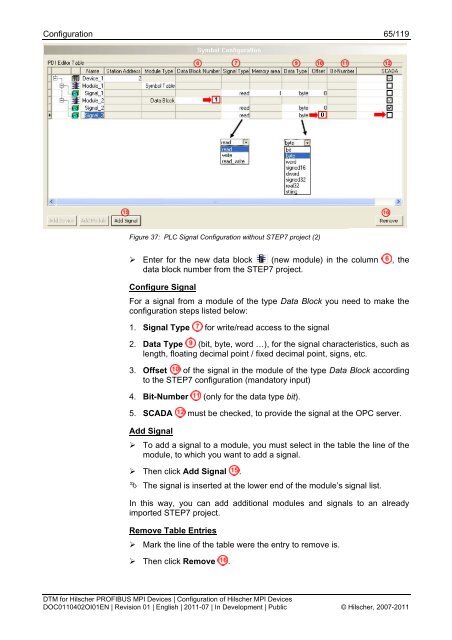
Figure 37: PLC Signal Configuration without STEP7 project (2)<br />
‣ Enter for the new data block (new module) in the column , the<br />
data block number from the STEP7 project.<br />
Configure Signal<br />
For a signal from a module of the type Data Block you need to make the<br />
configuration steps listed below:<br />
1. Signal Type for write/read access to the signal<br />
2. Data Type (bit, byte, word …), for the signal characteristics, such as<br />
length, floating decimal point / fixed decimal point, signs, etc.<br />
3. Offset of the signal in the module of the type Data Block according<br />
to the STEP7 configuration (mandatory input)<br />
4. Bit-Number (only for the data type bit).<br />
5. SCADA must be checked, to provide the signal at the OPC server.<br />
Add Signal<br />
‣ To add a signal to a module, you must select in the table the line of the<br />
module, to which you want to add a signal.<br />
‣ Then click Add Signal .<br />
The signal is inserted at the lower end of the module’s signal list.<br />
In this way, you can add additional modules and signals to an already<br />
imported STEP7 project.<br />
Remove Table Entries<br />
‣ Mark the line of the table were the entry to remove is.<br />
‣ Then click Remove .<br />
<strong>DTM</strong> for Hilscher <strong>PROFIBUS</strong> <strong>MPI</strong> Devices | Configuration of Hilscher <strong>MPI</strong> Devices<br />
DOC0110402OI01EN | Revision 01 | English | 2011-07 | In Development | Public © Hilscher, 2007-2011