user's manual for corhyd: an internal diffuser hydraulics model - IfH
user's manual for corhyd: an internal diffuser hydraulics model - IfH
user's manual for corhyd: an internal diffuser hydraulics model - IfH

You also want an ePaper? Increase the reach of your titles
YUMPU automatically turns print PDFs into web optimized ePapers that Google loves.
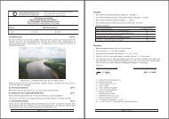
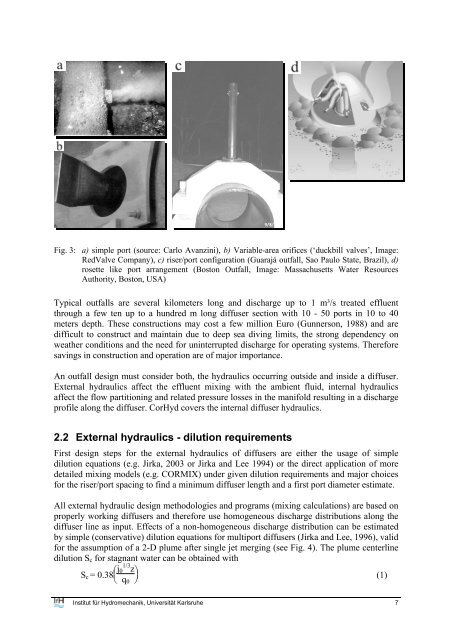
Fig. 3: a) simple port (source: Carlo Av<strong>an</strong>zini), b) Variable-area orifices (‘duckbill valves’, Image:<br />
RedValve Comp<strong>an</strong>y), c) riser/port configuration (Guarajá outfall, Sao Paulo State, Brazil), d)<br />
rosette like port arr<strong>an</strong>gement (Boston Outfall, Image: Massachusetts Water Resources<br />
Authority, Boston, USA)<br />
Typical outfalls are several kilometers long <strong>an</strong>d discharge up to 1 m³/s treated effluent<br />
through a few ten up to a hundred m long <strong>diffuser</strong> section with 10 - 50 ports in 10 to 40<br />
meters depth. These constructions may cost a few million Euro (Gunnerson, 1988) <strong>an</strong>d are<br />
difficult to construct <strong>an</strong>d maintain due to deep sea diving limits, the strong dependency on<br />
weather conditions <strong>an</strong>d the need <strong>for</strong> uninterrupted discharge <strong>for</strong> operating systems. There<strong>for</strong>e<br />
savings in construction <strong>an</strong>d operation are of major import<strong>an</strong>ce.<br />
An outfall design must consider both, the <strong>hydraulics</strong> occurring outside <strong>an</strong>d inside a <strong>diffuser</strong>.<br />
External <strong>hydraulics</strong> affect the effluent mixing with the ambient fluid, <strong>internal</strong> <strong>hydraulics</strong><br />
affect the flow partitioning <strong>an</strong>d related pressure losses in the m<strong>an</strong>ifold resulting in a discharge<br />
profile along the <strong>diffuser</strong>. CorHyd covers the <strong>internal</strong> <strong>diffuser</strong> <strong>hydraulics</strong>.<br />
2.2 External <strong>hydraulics</strong> - dilution requirements<br />
First design steps <strong>for</strong> the external <strong>hydraulics</strong> of <strong>diffuser</strong>s are either the usage of simple<br />
dilution equations (e.g. Jirka, 2003 or Jirka <strong>an</strong>d Lee 1994) or the direct application of more<br />
detailed mixing <strong>model</strong>s (e.g. CORMIX) under given dilution requirements <strong>an</strong>d major choices<br />
<strong>for</strong> the riser/port spacing to find a minimum <strong>diffuser</strong> length <strong>an</strong>d a first port diameter estimate.<br />
All external hydraulic design methodologies <strong>an</strong>d programs (mixing calculations) are based on<br />
properly working <strong>diffuser</strong>s <strong>an</strong>d there<strong>for</strong>e use homogeneous discharge distributions along the<br />
<strong>diffuser</strong> line as input. Effects of a non-homogeneous discharge distribution c<strong>an</strong> be estimated<br />
by simple (conservative) dilution equations <strong>for</strong> multiport <strong>diffuser</strong>s (Jirka <strong>an</strong>d Lee, 1996), valid<br />
<strong>for</strong> the assumption of a 2-D plume after single jet merging (see Fig. 4). The plume centerline<br />
dilution S c <strong>for</strong> stagn<strong>an</strong>t water c<strong>an</strong> be obtained with<br />
S c = 0.38⎜ ⎛ j 1/3 0 z<br />
⎝ q ⎠ ⎟⎞<br />
(1)<br />
0<br />
Institut für Hydromech<strong>an</strong>ik, Universität Karlsruhe 7