user's manual for corhyd: an internal diffuser hydraulics model - IfH
user's manual for corhyd: an internal diffuser hydraulics model - IfH
user's manual for corhyd: an internal diffuser hydraulics model - IfH

You also want an ePaper? Increase the reach of your titles
YUMPU automatically turns print PDFs into web optimized ePapers that Google loves.
should there<strong>for</strong>e result in feeder velocities v f,nf > 0.5 m/s (DIN EN 1671, ATV-DVWK-A 110<br />
(2001) <strong>an</strong>d ATV-DVWK-A 116 (2005)). This corresponds to a maximum feeder pipe<br />
diameter of D d,max = (Q nf 8/π) 0.5 ≈ 1,6 Q nf 0.5 . The feeder velocity <strong>for</strong> the far future design<br />
flowrate Q ff <strong>an</strong>d the same diameter results then in v f,ff = v f,nf Q ff /Q nf . Generally flowrates do<br />
not more th<strong>an</strong> double or triple during the lifetime of <strong>an</strong> outfall, so far field feeder velocities<br />
are from 1 to 2 m/s, what is clearly acceptable in terms of operational viewpoints considering<br />
the related energy losses.<br />
As the feeder also the <strong>diffuser</strong> pipe is constraint by a maximum scouring diameter.<br />
Theoretically this would result in a <strong>diffuser</strong> with different pipe segments as much as risers,<br />
<strong>an</strong>d, under the assumption of a homogeneous discharge distribution, each with a maximal<br />
diameter of D d,max,i = (8Q nf i/(Nπ)) 0.5 , where N denotes the total number of risers <strong>an</strong>d i the<br />
observed pipe section be<strong>for</strong>e the i-th riser starting counting offshore. Although best <strong>for</strong><br />
sediment removal this solution, also called tapering generally is too expensive to install (about<br />
20 % more exp<strong>an</strong>sive th<strong>an</strong> single diameter <strong>diffuser</strong>) <strong>an</strong>d maintain (i.e. cle<strong>an</strong>ing). Besides the<br />
continuous tapering after one or more br<strong>an</strong>ches the only alternative is decreasing the <strong>diffuser</strong><br />
diameter as a whole. Thus a simple configuration is achieved, although increased friction<br />
losses <strong>an</strong>d separation losses in the <strong>diffuser</strong> pipe will increase the total head. Ch<strong>an</strong>ges of the<br />
<strong>diffuser</strong> diameter cause only moderate ch<strong>an</strong>ges in the discharge profile. If tapering is applied<br />
the ch<strong>an</strong>ges in the discharge profile are even smaller th<strong>an</strong> in the case of ch<strong>an</strong>ging the diameter<br />
generally.<br />
By applying different diameters <strong>for</strong> CorHyd calculations it has to be considered, that pipes are<br />
not available in all sizes <strong>an</strong>d only diameters are applied which are given as <strong>internal</strong> diameters<br />
in catalogues of pipe producers.<br />
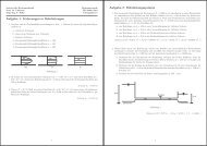
4.4 Port / Riser configurations<br />
Instead of typing in ports or risers one by one the concept of port/riser groups was used (Delft<br />
Hydraulics, 1995) <strong>for</strong> easy <strong>an</strong>d fast data input. The user should try to use as less groups as<br />
possible but as much as necessary to achieve optimized design.<br />
The total number of different groups is N g . For each port/riser group the number of used risers<br />
N gp <strong>an</strong>d the location on the <strong>diffuser</strong> pipe section has to be given. E.g. group number one<br />
consist of N gp = 15 risers each of them with the same specific port/riser configuration <strong>an</strong>d is<br />
mounted along the pipe section number one. Details of the parameter definitions are<br />
visualized in Fig. 15. The next input denotes the spacing L g between each group <strong>an</strong>d the<br />
spacing S between each riser in one group (often both are the same). It follows the input of<br />
the port elevation L r above the <strong>diffuser</strong> centerline (necessary <strong>for</strong> calculating the external<br />
pressure at the outlets). If no risers are applied the value should be zero. It follows the input<br />
<strong>for</strong> the port <strong>an</strong>d riser diameters D r , D p <strong>an</strong>d the roughness k s,r . If no risers are applied riser<br />
diameter <strong>an</strong>d roughness should be zero. If more th<strong>an</strong> one port is located at one position or at<br />
one riser the number of ports N p has to be given. If ports consist of little attached pipes their<br />
length L p <strong>an</strong>d related roughness k s,p should be given.<br />
A 50 mm minimum port size <strong>for</strong> secondary- or tertiary-level treated effluent <strong>an</strong>d storm water<br />
inflow to the sewage system was suggested by Wilkinson <strong>an</strong>d Wareham (1996) <strong>for</strong> avoiding<br />
the risk of blockage. Furthermore a minimum port size of 70 to 100 mm <strong>for</strong> primary treatment<br />
pl<strong>an</strong>ts (just screening <strong>an</strong>d settling t<strong>an</strong>k). The maximum port diameter should generally be<br />
smaller th<strong>an</strong> the <strong>diffuser</strong> pipeline diameter D d at upstream position to achieve higher<br />
discharge velocities <strong>an</strong>d avoid saltwater intrusion during low flows. The riser diameter D r<br />
Institut für Hydromech<strong>an</strong>ik, Universität Karlsruhe 39