user's manual for corhyd: an internal diffuser hydraulics model - IfH
user's manual for corhyd: an internal diffuser hydraulics model - IfH
user's manual for corhyd: an internal diffuser hydraulics model - IfH

Create successful ePaper yourself
Turn your PDF publications into a flip-book with our unique Google optimized e-Paper software.
2.4 M<strong>an</strong>ifold processes<br />
Pipe <strong>hydraulics</strong> are characterized by continuous pressure losses due to wall friction <strong>an</strong>d by<br />
local pressure losses due to geometrical ch<strong>an</strong>ges. M<strong>an</strong>ifold <strong>hydraulics</strong> (i.e. <strong>diffuser</strong>s) are<br />
characterized by several flow separations, where local losses depend not only on geometrical<br />
relations but furthermore on the discharge rates. The flow distribution <strong>for</strong> simple pipe<br />
configurations with uni<strong>for</strong>m geometries along the <strong>diffuser</strong> depends mainly on the ratio of<br />
br<strong>an</strong>ching losses <strong>an</strong>d m<strong>an</strong>ifold losses. But most of the actual <strong>diffuser</strong> geometries have more<br />
complex geometries. Diffusers often discharge fluids with higher or lower density th<strong>an</strong> the<br />
receiving waters, which cause <strong>an</strong> additional buoy<strong>an</strong>t <strong>for</strong>cing on the fluid flow.<br />
Implemented losses in CorHyd include continuous losses due to friction in all pipes (feeder,<br />
<strong>diffuser</strong>, riser, <strong>an</strong>d port). Local losses are considered automatically in all pipe sections, the<br />
feeder pipe, the <strong>diffuser</strong> m<strong>an</strong>ifold <strong>an</strong>d the attached port-riser br<strong>an</strong>ches. Furthermore additional<br />
local losses may be added <strong>m<strong>an</strong>ual</strong>ly if necessary:<br />
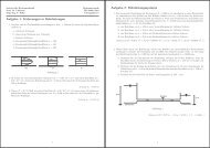
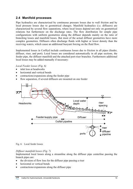
Local Feeder losses (Fig. 6)<br />
• inlet loss at headworks<br />
• horizontal <strong>an</strong>d vertical bends<br />
• contractions/exp<strong>an</strong>sions along the feeder pipe<br />
• flow separation, if several <strong>diffuser</strong>s are mounted on one feeder<br />
Fig. 6: Local feeder losses<br />
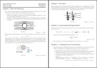
Diffuser m<strong>an</strong>ifold losses (Fig. 7)<br />
Implemented local losses along a streamline along the <strong>diffuser</strong> pipe centerline passing the<br />
br<strong>an</strong>ch pipes are:<br />
• the division of flow loss <strong>for</strong> the <strong>diffuser</strong> pipe passing a riser<br />
• horizontal or vertical bends<br />
• contractions/exp<strong>an</strong>sions along the <strong>diffuser</strong> pipe<br />
Institut für Hydromech<strong>an</strong>ik, Universität Karlsruhe 10