user's manual for corhyd: an internal diffuser hydraulics model - IfH
user's manual for corhyd: an internal diffuser hydraulics model - IfH
user's manual for corhyd: an internal diffuser hydraulics model - IfH

Create successful ePaper yourself
Turn your PDF publications into a flip-book with our unique Google optimized e-Paper software.
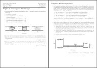
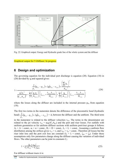
Fig. 22: Graphical output: Energy <strong>an</strong>d Hydraulic grade line of the whole system <strong>an</strong>d the <strong>diffuser</strong><br />
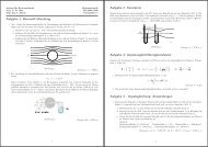
Graphical output <strong>for</strong> T-Diffuser: In progress<br />
6 Design <strong>an</strong>d optimization<br />
The governing equation <strong>for</strong> the individual port discharge is equation (20). Equation (18) in<br />
(20) devided by q i <strong>an</strong>d squared gives:<br />
i<br />
⎛ ⎞<br />
⎜∑<br />
q<br />
k ⎟<br />
2<br />
=<br />
( ) ( )<br />
⎝ k 1 ⎠<br />
p<br />
d,i<br />
− p<br />
a,i<br />
+ 2g z<br />
d,i<br />
− z<br />
jet,i<br />
+<br />
2<br />
ρ<br />
e<br />
A<br />
d,i<br />
1 =<br />
(24)<br />
2<br />
2<br />
2 2 n p,i<br />
n<br />
⎛ ⎞ ⎛ λ ⎞<br />
r ,i<br />
q α<br />
⎛ ⎞ ⎛ λ ⎞<br />
i i<br />
∑⎜<br />
q α<br />
p,i, jL<br />
i i<br />
p,i, j<br />
r,i, j r,i, j<br />
+ ⎟ ⎜ζ<br />
+ ⎟ + ∑⎜<br />
q<br />
L<br />
i<br />
⎟ ⎜ζ<br />
+ ⎟<br />
2<br />
( )<br />
p,i, j<br />
r,i, j<br />
C A<br />
j=<br />
1 ⎝ A<br />
p,i, j ⎠ ⎝ D<br />
p,i, j ⎠ j=<br />
1 ⎝ A<br />
r,i, j ⎠ ⎝ D<br />
r,i, j ⎠<br />
c,i<br />
p,i<br />
where the losses along the <strong>diffuser</strong> are included in the <strong>internal</strong> pressure p d,i from equation<br />
(18).<br />
The first two terms in the numerator denote the difference of the piezometric head (hydraulic<br />
2<br />
head) ( p<br />
d,i<br />
− p<br />
a,i<br />
) + 2g( z<br />
d,i<br />
− z<br />
jet, i<br />
) = ∆ i between the <strong>diffuser</strong> <strong>an</strong>d the ambient. The third term<br />
ρ<br />
e<br />
in the numerator is related to the <strong>diffuser</strong> velocities v d,i . The terms in the denominator are<br />
related to the jet velocity v j , i = α i q i /(C c A p,i ) <strong>an</strong>d the port <strong>an</strong>d riser losses. For outfalls with<br />
uni<strong>for</strong>m geometries or <strong>for</strong> uni<strong>for</strong>m <strong>diffuser</strong> sections with uni<strong>for</strong>m port/riser groups it follows<br />
A i = A = const., α i = α = const., D i = D = const., L i = L = const.. Assuming a uni<strong>for</strong>m flow<br />
distribution among the orifices gives v r,i = v r <strong>an</strong>d v p,i = v p = const.. There<strong>for</strong>e all losses but the<br />
riser inlet loss <strong>an</strong>d the port exit loss are const<strong>an</strong>t (λ i = λ = const., ζ p,i = ζ p ). Under these<br />
assumptions only few parameters ch<strong>an</strong>ge along the <strong>diffuser</strong> causing the variation of individual<br />
flows. The other parameters c<strong>an</strong> be joint in const<strong>an</strong>ts C i :<br />
1 =<br />
∆ i + v d,i ²<br />
C 1 /C c,i 2 + C 2 ζ dr,i<br />
(25)<br />
For <strong>diffuser</strong> without risers it is:<br />
Institut für Hydromech<strong>an</strong>ik, Universität Karlsruhe 46<br />
2