Wilkinson, D. L., “Purging of saline wedges from oce<strong>an</strong> outfalls”, Journal of Hydraulic Engineering, Vol 110, No. 12, December, 1984 Wilkinson, D. L., “Seawater circulation in sewage outfall tunnels”, Journal of Hydraulic Engineering, Vol. 111, No. 5, May, 1985 Wilkinson, D. L., Wareham, David G., “Optimization Criteria <strong>for</strong> Design of Coastal City Wastewater Disposal Systems”, Proc. Cle<strong>an</strong> Sea 96, Toyohashi, 1996 Wilkinson, D.L. & Wareham, D.G, “Optimization of Coastal City Wastewater Treatment <strong>an</strong>d Disposal Systems to Achieve Sustainable Development”, Proc. of the 1998 IPENZ Conference, 12-16 February, 1998, p 6.3-6.7 Wilkinson, D.L., Nittim, R., "Model studies of outfall riser <strong>hydraulics</strong>", Journal of Hydraulic Research, Vol. 30, No. 5, 1992 Williams, B.L., 1985 "Oce<strong>an</strong> Outfall H<strong>an</strong>dbook", National Water <strong>an</strong>d Soil Conservation Authority, Water&Soil Miscell<strong>an</strong>eous publication number 76, Wellington Wood, I.R.; Bell R.G.; Wilkinson D.L., “Oce<strong>an</strong> Disposal of wastewater”, World Scientific, Singapore, 1993 WRc, "Design Guide <strong>for</strong> Marine Treatment Schemes", Water Research Centre plc., Swindon, 1990 Institut für Hydromech<strong>an</strong>ik, Universität Karlsruhe 75
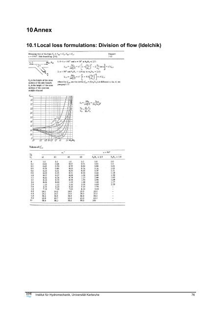
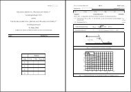
10 Annex 10.1 Local loss <strong>for</strong>mulations: Division of flow (Idelchik) Institut für Hydromech<strong>an</strong>ik, Universität Karlsruhe 76
- Page 1 and 2:
Universität Karlsruhe Institut fü
- Page 3 and 4:
Acknowledgments The authors like to
- Page 5 and 6:
10.1 Local loss formulations: Divis
- Page 7 and 8:
1 Introduction CorHyd is a computer
- Page 9 and 10:
Fig. 1: Outfall configuration showi
- Page 11 and 12:
where j 0 denotes the buoyancy flux
- Page 13 and 14:
2.4 Manifold processes Pipe hydraul
- Page 15 and 16:
Fig. 8: Local port/riser branch los
- Page 17 and 18:
Table 2: Local loss formulations Ty
- Page 19 and 20:
Gradual contraction (Idelchik 1986)
- Page 21 and 22:
Where H denotes the headloss, V duc
- Page 23 and 24:
Table 3: Equivalent sand roughness
- Page 25 and 26:
Institut für Hydromechanik, Univer
- Page 27 and 28: For a constant sea water level and
- Page 29 and 30: (16) solved for r in (15) and assum
- Page 31 and 32: 3.1.4 Automatic implementation of l
- Page 33 and 34: elevation difference between diffus
- Page 35 and 36: The iteration stops if the differen
- Page 37 and 38: Table 4: CorHyd subroutines and the
- Page 39 and 40: 4 Data Input Input can either be do
- Page 41 and 42: (ρ 0,max > ρ 0 ). Further sensiti
- Page 43 and 44: should allow for riser velocities,
- Page 45 and 46: Fig. 19: First input sub-window for
- Page 47 and 48: 10 7050.000 0.000 -2.500 11 7000.00
- Page 49 and 50: Fig. 22: Graphical output: Energy a
- Page 51 and 52: given dilution requirements and maj
- Page 53 and 54: 6.3 Off design conditions It was co
- Page 55 and 56: Table 5: Sensitivity of involved pa
- Page 57 and 58: Fig. 24: Side view and cross sectio
- Page 59 and 60: Fig. 27: Flow characteristics for d
- Page 61 and 62: under different flow conditions. Th
- Page 63 and 64: Fig. 32: Side view and cross sectio
- Page 65 and 66: Fig. 34: Flow characteristics for:
- Page 67 and 68: Fig. 36: Flow characteristics for:
- Page 69 and 70: Fig. 38: Flow characteristics for:
- Page 71 and 72: Table 6: Comparison of construction
- Page 73 and 74: seaward end, which can be prevented
- Page 75 and 76: Especially for this long diffuser a
- Page 77: Jirka, G.H., Doneker, R.L. and Hint
- Page 81 and 82: Institut für Hydromechanik, Univer
- Page 83 and 84: Institut für Hydromechanik, Univer