user's manual for corhyd: an internal diffuser hydraulics model - IfH
user's manual for corhyd: an internal diffuser hydraulics model - IfH
user's manual for corhyd: an internal diffuser hydraulics model - IfH

You also want an ePaper? Increase the reach of your titles
YUMPU automatically turns print PDFs into web optimized ePapers that Google loves.
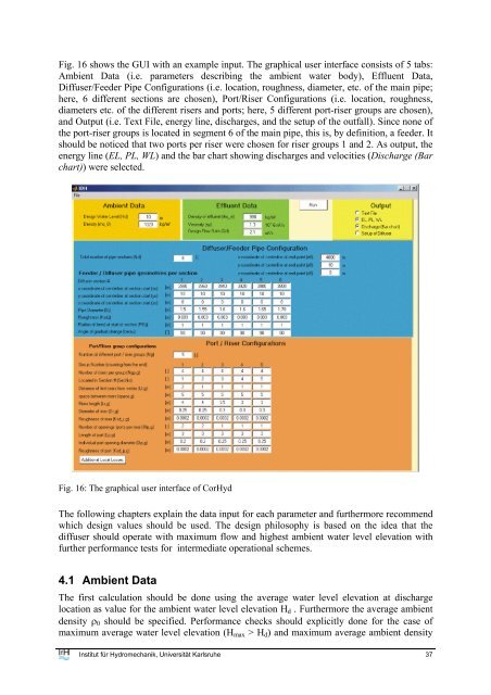
Fig. 16 shows the GUI with <strong>an</strong> example input. The graphical user interface consists of 5 tabs:<br />
Ambient Data (i.e. parameters describing the ambient water body), Effluent Data,<br />
Diffuser/Feeder Pipe Configurations (i.e. location, roughness, diameter, etc. of the main pipe;<br />
here, 6 different sections are chosen), Port/Riser Configurations (i.e. location, roughness,<br />
diameters etc. of the different risers <strong>an</strong>d ports; here, 5 different port-riser groups are chosen),<br />
<strong>an</strong>d Output (i.e. Text File, energy line, discharges, <strong>an</strong>d the setup of the outfall). Since none of<br />
the port-riser groups is located in segment 6 of the main pipe, this is, by definition, a feeder. It<br />
should be noticed that two ports per riser were chosen <strong>for</strong> riser groups 1 <strong>an</strong>d 2. As output, the<br />
energy line (EL, PL, WL) <strong>an</strong>d the bar chart showing discharges <strong>an</strong>d velocities (Discharge (Bar<br />
chart)) were selected.<br />
Fig. 16: The graphical user interface of CorHyd<br />
The following chapters explain the data input <strong>for</strong> each parameter <strong>an</strong>d furthermore recommend<br />
which design values should be used. The design philosophy is based on the idea that the<br />
<strong>diffuser</strong> should operate with maximum flow <strong>an</strong>d highest ambient water level elevation with<br />
further per<strong>for</strong>m<strong>an</strong>ce tests <strong>for</strong> intermediate operational schemes.<br />
4.1 Ambient Data<br />
The first calculation should be done using the average water level elevation at discharge<br />
location as value <strong>for</strong> the ambient water level elevation H d . Furthermore the average ambient<br />
density ρ 0 should be specified. Per<strong>for</strong>m<strong>an</strong>ce checks should explicitly done <strong>for</strong> the case of<br />
maximum average water level elevation (H max > H d ) <strong>an</strong>d maximum average ambient density<br />
Institut für Hydromech<strong>an</strong>ik, Universität Karlsruhe 37