special - ALUMINIUM-Nachrichten – ALU-WEB.DE
special - ALUMINIUM-Nachrichten – ALU-WEB.DE
special - ALUMINIUM-Nachrichten – ALU-WEB.DE

Create successful ePaper yourself
Turn your PDF publications into a flip-book with our unique Google optimized e-Paper software.
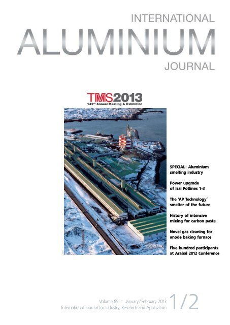
Special: aluminium<br />
smelting industry<br />
power upgrade<br />
of isal potlines 1-3<br />
The ‘ap Technology’<br />
smelter of the future<br />
History of intensive<br />
mixing for carbon paste<br />
Novel gas cleaning for<br />
anode baking furnace<br />
ABB<br />
Five hundred participants<br />
at arabal 2012 conference<br />
Volume 89 · January / February 2013<br />
International Journal for Industry, Research and Application1/2
Melting Furnaces<br />
State-of-the-art scrap and dross remelting<br />
Leading technology in the aluminum casthouse<br />
There are many benefi <br />
<br />
<br />
<br />
<br />
fi <br />
<br />
<br />
Major benefits<br />
<br />
<br />
<br />
<br />
<br />
Common features and advantages of<br />
Hertwich melting furnaces<br />
<br />
<br />
Integrated scrap preheating and gasifi<br />
<br />
<br />
<br />
<br />
<br />
<br />
<br />
<br />
HERTWICH ENGINEERING GMBH
CONTENTS<br />
Volker Karow<br />
Chefredakteur<br />
Editor in Chief<br />
Aluminiumindustrie<br />
startet optimistisch<br />
ins neue Jahr<br />
Optimistic start for the<br />
aluminium industry<br />
in the new year<br />
Aktuelle Zahlen zum globalen Wirtschaftswachstum<br />
2012 lagen bei Redaktionsschluss<br />
zwar noch nicht vor, doch gehen die meisten<br />
Volkswirte von einem Zuwachs um die drei<br />
Prozent aus. Ob die Weltkonjunktur 2013<br />
weiter an Fahrt gewinnen wird, darüber gehen<br />
die Einschätzungen auseinander. Weitgehende<br />
Einigkeit besteht darin, dass Europas<br />
Wirtschaft erneut schrumpfen wird, die USA<br />
moderat wachsen werden und die Konjunktur<br />
in den Schwellenländern wieder anzieht.<br />
Für den Aluminiummarkt zeigt sich Alcoa-<br />
Chef Klaus Kleinfeld optimistisch. Die globale<br />
Nachfrage nach Aluminium, so seine Einschätzung,<br />
werde im laufenden Jahr um sieben<br />
Prozent steigen. Das reicht zwar nicht an die<br />
Werte von 2010 (+13%) und 2011 (+10%)<br />
heran, wäre aber ein Prozentpunkt über dem<br />
geschätzten Zuwachs von 2012. Getragen<br />
werde diese Entwicklung vor allem von der<br />
Nachfrage aus der Luftfahrt- und Bauindustrie.<br />
Für den Luftfahrtmarkt rechnet Alcoa mit<br />
einem fast zweistelligen Wachstum.<br />
Andere Aluminiumkonzerne sind allerdings<br />
nicht ganz so optimistisch in ihren Prognosen<br />
für das laufende Jahr. Hydro-Chef<br />
Svein Richard Brandtzæg bezifferte den Zuwachs<br />
der globalen Aluminiumnachfrage auf<br />
einer Investorenveranstaltung Ende November<br />
bei zwei bis vier Prozent <strong>–</strong> ohne China.<br />
Bei den Aluminiumpreisen zeichnet sich<br />
seit einigen Monaten eine leichte Erholung<br />
ab. Die 3-Monats-Notierungen haben sich<br />
von ihrem Tief im August ($1.831/t) abgesetzt,<br />
sie lagen Mitte Januar bei 2.094 Dollar<br />
je Tonne. Angesichts hoher weltweiter Lagerbestände<br />
und des weiteren Zubaus von<br />
Produktionskapazitäten <strong>–</strong> Beispiel Alcoa<br />
Ma’aden: Die neue Hütte in Saudi-Arabien<br />
hat im Dezember ihren ersten von 720 Elektrolyseöfen<br />
in Betrieb genommen <strong>–</strong> ist der<br />
Spielraum für substanzielle Preissprünge<br />
begrenzt. Dies hält den Druck auf die Erlöse<br />
hoch; kaum ein Branchenunternehmen, dass<br />
nicht Effizienzprogramme fährt, um Kosten<br />
zu senken.<br />
Stetiger technologischer Fortschritt trägt<br />
maßgeblich dazu bei, noch produktiver bzw.<br />
kostensparender zu produzieren. Dass die<br />
Hüttenbranche und ihre Ausrüster kontinuierlich<br />
daran arbeiten, ihre Produktion<br />
und Arbeitsabläufe immer effizienter zu gestalten,<br />
belegen zahlreiche Beiträge in dieser<br />
Ausgabe.<br />
Pro domo: Der besseren Lesbarkeit wegen<br />
werden rein englischsprachige Artikel ab<br />
dieser Ausgabe schwarz gedruckt. Deutschenglische<br />
Beiträge wie in diesem Editorial behalten<br />
dagegen ihre farbige Unterscheidung.<br />
Although the latest figures for global economic<br />
growth in 2012 were not yet available<br />
when we last went to press, most economists<br />
anticipate that growth will have amounted to<br />
around three percent. Whether world trade<br />
will again pick up speed in 2013 is a question<br />
on which opinions differ. It is generally<br />
agreed, however, that Europe’s economy will<br />
again contract, the USA will see moderate<br />
growth and trade in the developing countries<br />
will continue its upward trend.<br />
As regards the aluminium market, Alcoa<br />
CEO Klaus Kleinfeld is optimistic. During<br />
the presentation of his company’s quarterly<br />
results his estimation was that demand for<br />
aluminium will rise seven percent this year.<br />
Although that does not come up to the values<br />
in 2010 (+13%) and 2011 (+11%), it would<br />
still be a percentage point higher than the<br />
estimated growth in 2012. That development<br />
is driven above all by demand from the aviation<br />
and building sectors. In the aviation market<br />
Alcoa expects growth to reach almost the<br />
two-digit level.<br />
Other aluminium concerns, however, are<br />
not quite so optimistic in their forecasts for<br />
this year. At an investor conference in November<br />
Svein Richard Brandtzæg, CEO of<br />
Hydro, put a figure of two to four percent<br />
on the growth of global demand for aluminium<br />
<strong>–</strong> leaving China aside. That would correspond<br />
to the level of general expectations<br />
regarding world trade.<br />
In recent months aluminium prices have<br />
shown a slight recovery. From their low-point<br />
in August (USD1,831/t), 3-month quotes have<br />
improved somewhat and in mid-January stood<br />
at USD2,094/t. In light of high aluminium<br />
stock levels worldwide and further proliferation<br />
of production capacities <strong>–</strong> for example,<br />
Alcoa Ma’aden: in mid-December the new<br />
smelter in Saudi Arabia started up the first of<br />
its 720 pots cells <strong>–</strong> the scope for substantial<br />
price increases is limited. This maintains the<br />
high pressure on profits: almost every aluminium<br />
company today is busy implementing<br />
efficiency measures to cut costs.<br />
Continual technological advances are contributing<br />
decisively toward increased productivity<br />
and cost-cutting. Many articles in this issue<br />
bear witness that the smelter industry and<br />
its suppliers are constantly striving to make<br />
their production and working procedures<br />
ever more efficient.<br />
Editor’s note: As from this issue, articles purely<br />
in English will be printed in black to facilitate<br />
legibility. Contributions in both German<br />
and English, however, such as this editorial,<br />
will retain their colour demarcation.<br />
<strong><strong>ALU</strong>MINIUM</strong> · 1-2/2013 3
INHALT<br />
EDITORIAL<br />
Aluminiumindustrie startet optimistisch ins neue Jahr<br />
Optimistic start for the aluminium industry in the new year ................ 3<br />
AKTUELLES • NEWS IN BRIEF<br />
GF Automotive veräußert deutsches Sandgussgeschäft ......................... 6<br />
8<br />
Aluminium China’s buyer delegations demand<br />
for high quality equipment from overseas ......................................... 7<br />
12 th OEA International Aluminium<br />
Recycling Congress in Düsseldorf, 25-26 Feb 2013 .............................. 7<br />
Amag errichtet Logistikzentrum in Rekordzeit .................................... 8<br />
14 to 18 May 2013, Milano, Italy:<br />
8 th Aluminium Two Thousand Congress ............................................. 9<br />
WIRTSCHAFT • ECONOMICS<br />
Aluminiumpreise ......................................................................... 10<br />
Produktionsdaten der deutschen Aluminiumindustrie ..........................12<br />
Five hundred participants at Arabal 2012 Conference .........................14<br />
Dubal’s DX+ technology selected by Alba ........................................15<br />
TMS2013 offers a diversity of light metals<br />
programming and networking opportunities ....................................16<br />
<strong><strong>ALU</strong>MINIUM</strong> SMELTING INDUSTRY<br />
Recent development of Dubal<br />
aluminium reduction cell technologies ............................................18<br />
0<br />
The ‘AP Technology’ smelter of the future .......................................24<br />
Möller direct pot feeding system for<br />
greenfield and brownfield smelters ................................................28<br />
Carbone Savoie <strong>–</strong> Cathode producer shows its metal .........................32<br />
Fives Solios <strong>–</strong> 30 years of experience in fume desulphurisation ...........38<br />
Alumina refinery: Outotec’s process and implementation solution .......33<br />
Eirich: History of intensive mixing for carbon paste ..........................40<br />
HMR’s automated stud repair line ..................................................44<br />
Marx: Channel-type versus coreless induction furnace .......................46<br />
Alcoa starts up potlining facility at Fjardaál Iceland smelter ...............49<br />
Gautschi Engineering <strong>–</strong> An industry profile ......................................52<br />
Latest News<br />
www.alu-web.de<br />
Advanced technology from Brochot <strong>–</strong><br />
A proven solution for anode slot cutting .........................................56<br />
Diffusion and convection of alumina<br />
in the bath of a Hall-Héroult cell ...................................................58<br />
4 <strong><strong>ALU</strong>MINIUM</strong> · 1-2/2013 · 4/2012
CONTENTS<br />
Power upgrade of Isal Potlines 1-3 .................................................61<br />
Applying computational thermodynamics<br />
to industrial aluminium alloys ..........................................64<br />
ECL <strong>–</strong> A privileged equipment supplier to the aluminium industry .......67<br />
Alstom Power <strong>–</strong> Novel gas cleaning for anode baking furnace ............70<br />
GNA cathode block sealing process ................................................72<br />
T. T. Tomorrow <strong>–</strong> Slotting anodes and recycling carbon ......................74<br />
Testing a new ‘STARprobe’............................................................76<br />
Carbothermic reduction <strong>–</strong> An alternative<br />
aluminium production process .......................................................76<br />
52<br />
Recycling of smelter materials through<br />
rotary crushing and material separation ..........................................82<br />
Meeting of the ISO Committee for analysis of<br />
materials for primary aluminium in Switzerland ................................86<br />
TECHNOLOGIE • TECHNOLOGY<br />
Chips versus briquettes: How the aluminium<br />
industry can effectively and efficiently recycle scrap ..........................87<br />
82<br />
Bühler Lost-Core-Technologie eröffnet weites Anwendungsspektrum<br />
Bühler Lost Core technology opens up a wide range of applications ....89<br />
GM welding innovation enables increased use of aluminium ...............90<br />
APPLICATION<br />
Aluminium: Tesla’s secret weapon in new Model S ...........................91<br />
COMPANY NEWS WORLDWI<strong>DE</strong><br />
Aluminium smelting industry .........................................................92<br />
Bauxite and alumina activities ......................................................92<br />
Aluminium semis .........................................................................93<br />
On the move ..............................................................................93<br />
Suppliers ...................................................................................94<br />
RESEARCH<br />
Cathode wear in Hall-Héroult cells .................................................95<br />
DOCUMENTATION<br />
Patente .....................................................................................98<br />
Impressum • Imprint .................................................................. 113<br />
Vorschau • Preview ................................................................... 114<br />
LIEFERVERZEICHNIS • SUPPLIERS DIRECTORY ........... 100<br />
Inserenten dieser Ausgabe<br />
List of advertisers<br />
ABB Switzerland 37<br />
Alteco Aluminiumtechnologie, Austria 22<br />
Buss AG, Switzerland 21<br />
De Winter Engineering, The Netherlands 60<br />
Didion International Inc., USA 17<br />
Dubai Aluminium Co. Ltd , UAE 13<br />
Fives Solios, France 41<br />
FLSmidth Hamburg GmbH, Germany 45<br />
Gautschi Engineering, Switzerland 29<br />
Glama Maschinenbau GmbH, Germany 53<br />
Hertwich Engineering GmbH, Austria 2<br />
Inotherm Industrieofen- und<br />
Wärmetechnik GmbH, Germany 87, 91<br />
Innovatherm Prof. Dr. Leisenberg<br />
GmbH & Co. KG, Germany 35<br />
Interall Srl, Italy 31<br />
Precimeter Control AB, Sweden 65<br />
R&D Carbon Ltd, Switzerland 116<br />
Reed Exhibitions China Ltd, PR China 11<br />
Reed Exhibitions, UAE 115<br />
Riedhammer GmbH, Germany 19<br />
SMS Siemag AG, Germany 50/51<br />
TMS Minerals, Metals<br />
& Materials Society, USA 23<br />
T.T. Tomorrow Technology SpA, Italy 25<br />
<strong><strong>ALU</strong>MINIUM</strong> · 4/2012 1-2/2013 5
AKTUELLES<br />
GF Automotive veräußert deutsches Sandgussgeschäft<br />
Künftiger Fokus auf Druckgussgeschäft in Asien und Europa<br />
© Georg Fischer<br />
GF Automotive hat sein deutsches Aluminiumsandgussgeschäft<br />
mit den Gießereien in<br />
Friedrichshafen und Garching veräußert. In<br />
Zukunft will sich das zum Industriekonzern<br />
Georg Fischer gehörende Unternehmen auf<br />
seine Eisen- und Aluminium-Druckgießereien<br />
in Europa konz und vor allem seine bestehenden<br />
Werke in China weiter ausbauen.<br />
Im Werk Friedrichshafen von GF Automotive werden Antriebs- und Fahrwerksteile<br />
aus Aluminiumsandguss hergestellt<br />
Georg Fischer erwartet in naher Zukunft<br />
weiteres Wachstum vor allem am asiatischen<br />
Automobilmarkt und eine eher verhaltene<br />
Marktlage in Europa. Daher soll die rasche<br />
Expansion in China fortgesetzt werden. Der<br />
Anteil des Landes am Umsatz von GF Automotive<br />
ist in den letzten sechs Jahren von null<br />
auf zehn Prozent gestiegen. Die Produktionskapazitäten<br />
der beiden bestehenden Eisenund<br />
Aluminiumdruckgießereien sollen in den<br />
nächsten zwei Jahren um 40 Prozent erweitert<br />
werden.<br />
In Europa will<br />
sich das Unternehmen<br />
auf Aktivitäten<br />
konzentrieren, bei<br />
denen bereits eine<br />
führende Marktposition<br />
erreicht wurde<br />
oder künftig erreicht<br />
werden kann.<br />
Dies trifft für das<br />
Druckgussgeschäft<br />
zu, nicht jedoch für<br />
das Aluminiumsandgussgeschäft.<br />
Die<br />
beiden Werke in<br />
Friedrichshafen und<br />
Garching werden<br />
an die MWS Industrieholding<br />
GmbH veräußert, die damit zum<br />
Technologieführer und größten Anbieter im<br />
Bereich Aluminiumsandguss in Europa wird.<br />
Yves Serra, CEO von Georg Fischer, erklärte:<br />
„Die Integration der Aluminiumsandgussaktivitäten<br />
in das Geschäft von MWS hat eine<br />
bedeutende Konsolidierung innerhalb dieses<br />
Marktsegments zur Folge und erlaubt es GF<br />
Automotive, sich auf ihre Kernaktivitäten<br />
zu konzentrieren.“ Um die Kontinuität des<br />
Geschäfts zu gewährleisten soll das bisherige<br />
Sandguss-Management laut MWS an Bord<br />
bleiben.<br />
Die Gießereien in Friedrichshafen und Garching<br />
gehören seit 1999 zum Georg Fischer<br />
Konzern und beschäftigen 250 bzw. 180 Mitarbeiter.<br />
Sie sind auf Aluminiumsandgussteile<br />
für Pkw, Nutzfahrzeuge und Industrieanwendungen<br />
spezialisiert. Der Gesamtumsatz der<br />
beiden Gießereien belief sich 2011 auf 127<br />
Mio. Schweizer Franken. GF Automotive verzeichnete<br />
2011 einen Umsatz von 1,7 Mrd.<br />
Schweizer Franken.<br />
Die MWS-Gruppe mit Sitz in Kufstein-<br />
Schwoich ist ein österreichischer Automobilzulieferer<br />
in Privatbesitz. Die Gruppe ist auf<br />
Aluminiumguss spezialisiert. MWS wurde<br />
2004 gegründet und verfügt derzeit über drei<br />
Niederlassungen in Österreich und ein Produktionswerk<br />
in der Slowakei. Das Unternehmen<br />
hat insgesamt 320 Beschäftigte und<br />
erzielte 2012 einen Umsatz von 32 Millionen<br />
Euro.<br />
Otto Junker und Can-Eng<br />
Furnaces kooperieren<br />
beim Service<br />
Die Otto Junker Gruppe, Simmerath, und<br />
Can-Eng Furnaces International Ltd., Niagara<br />
Falls / Ontario, kooperieren beim Kundendienst.<br />
Eine jüngst abgeschlossene Vereinbarung<br />
zielt angesichts der sich wechselseitig<br />
ergänzenden Produktpaletten darauf, die<br />
Betreiber von Junker- bzw. Can-End-Wärmebehandlungsanlagen<br />
in aller Welt besser zu<br />
unterstützen. Den Kunden bietet sich damit<br />
eine komplette Palette von Schmelz-, Gieß-,<br />
Prozesserwärmungs- und Wärmebehandlungsanlagen<br />
für thermische Verfahrensanwendungen.<br />
Im Rahmen des Kundendienstes können<br />
Kunden von Otto Junker und Can-Eng ihre<br />
Anfragen zu Produkten der beiden Gruppen<br />
jeweils an die geografisch nächstgelegene Vertriebsniederlassung<br />
richten. Hauptansprechpartner<br />
sind Tim Donofrio (Vice President,<br />
Standard and Aluminium Products, Can-Eng<br />
Furnaces, tdonofrio@can-eng.com), und Jan<br />
van Treek (Verkauf Thermoprozessanlagen,<br />
Otto Junker jvt@otto-junker.de).<br />
Alu.Heat baut innovative<br />
Pilot-Wärmebehandlungsanlage<br />
Die Alu.Heat GmbH hat eine innovative Pilotanlage<br />
zur Wärmebehandlung gebaut, die aus<br />
einem luftumgewälzten Kammerofen, einer<br />
Luft-/Wasserdusche, einem Wasserabschreckbad<br />
mit Umwälzung, einer automatischen Beschickungseinrichtung<br />
und einer Prozesssteuerung<br />
mit entsprechender Dokumentation besteht.<br />
Mit der zum Patent angemeldeten Luftabschreckung<br />
unter Zugabe einer regelbaren<br />
Wassermenge wurden die Möglichkeiten zur<br />
Optimierung mechanischer Kennwerte deutlich<br />
erweitert. Damit entstand eine Pilotanlage,<br />
die den Wärmebehandlungsprozess in der<br />
Praxis realistisch nachbildet und die Kunden<br />
in ihrer F&E-Arbeit unterstützt.<br />
Der gesamte Wärmebehandlungsprozess <strong>–</strong><br />
das Zusammenspiel von Temperatur, Zeit und<br />
Abschreckung sowie die Planung des gesamten<br />
Ablaufes <strong>–</strong> wird individuell auf das Bauteil<br />
des Kunden bezogen und wissenschaftlich<br />
dokumentiert. Die Alu.Heat-Kunden können<br />
somit Versuche fahren, ohne ihre laufenden<br />
Prozesse innerbetrieblich zu stören. Durch<br />
gezielte Versuche und die Kombination aller<br />
technischen Möglichkeiten können deutliche<br />
Gewichtsreduzierungen pro Bauteil erzielt<br />
werden. Einhergehend mit der Einsparung<br />
von Gewicht und damit Material wird der<br />
Energieverbrauch, bspw. eines Fahrzeugs, reduziert,<br />
die Langlebigkeit des Bauteils erhöht,<br />
seine Belastungsgrenze ausgedehnt und die<br />
CO 2 -Emission reduziert.<br />
6 <strong><strong>ALU</strong>MINIUM</strong> · 1-2/2013
NEWS IN BRIEF<br />
Aluminium China’s buyer delegations demand<br />
for high quality equipment from overseas<br />
© Reed Exhibitions<br />
In 2013, ‘Aluminium China’, the leading aluminium<br />
sourcing platform in Asia for industry<br />
professionals and buyers from the aluminium<br />
industry and a wide array of application industries<br />
will expand its buyer delegation programmes<br />
on further key Asian industry clusters<br />
in China, South East Asia and India.<br />
More than 14,700 visitors attended the Aluminum China 2012 trade fair<br />
Thanks to the success of Reed Exhibition<br />
China’s Targeted Attendee Programme for<br />
Chinese VIP buyers at Aluminium China<br />
2012, over 200 exhibitors already booked exhibition<br />
space for the 2013 event occupying<br />
80% of the overall exhibition space. Jiasheng<br />
Wang, managing director of Ebner Industrial<br />
Furnaces (Taicang), commented on the sidelines<br />
of the 2012 event: “Aluminium China is<br />
a great platform for us. Although there are numerous<br />
trade exhibitions in China every year,<br />
we only exhibit at a single aluminium event:<br />
this one. We’ll exhibit here again next year.”<br />
With its still booming economy, China is<br />
set to remain the world’s largest aluminium<br />
consumer throughout the next several years,<br />
accounting for more<br />
than 40% of global<br />
aluminium consumption.<br />
Carmakers like<br />
VW, BMW, Audi<br />
and Nissan are set<br />
to open new production<br />
plants in China<br />
within the next two<br />
years, and numerous<br />
construction projects<br />
are planned for the<br />
country’s western<br />
provinces. China’s<br />
main application industry<br />
sectors for<br />
aluminium are set to<br />
drive demand for both<br />
finished and semi-finished products, but also<br />
for processing machinery and equipment from<br />
Japan, Korea and Europe. As a consequence<br />
of rising energy costs an increasing number of<br />
Chinese aluminium producing and processing<br />
manufacturers have expressed strong intend<br />
to buy modern, energy saving machinery and<br />
equipment from overseas.<br />
The organiser of Aluminium China 2013<br />
will leverage this strong demand and invite<br />
an even bigger number of 550 targeted top<br />
buyers from China as well as procurement<br />
delegations from selected application industry<br />
sectors in Asia, for pre-arranged matchmaking<br />
sessions with international exhibitors.<br />
This combination of the supply and demand<br />
side of the aluminium industry will present a<br />
number of attractive business opportunities to<br />
both parties. Reed Exhibition’s international<br />
delegation programme for Aluminium China<br />
2013 includes new partnerships with tour operators<br />
and buying associations from countries<br />
with increasing demand for equipment and<br />
aluminium products: India, South East Asia<br />
and Russia.<br />
For Aluminium China 2013 the blend of<br />
material exhibitions, high profile conferences<br />
and the complementary trade exhibitions<br />
Copper China 2013 and Magnesium China<br />
2013 will again enhance the show’s success.<br />
Additionally, the ‘China Aluminium Fabrication<br />
Forum’, organised by the China Metal<br />
Information Network, and a new edition of<br />
the Lightweight Automotive Forum will give<br />
participants a synergetic opportunity to source<br />
and display diversified exhibits while learning<br />
more about the key issues affecting today’s<br />
aluminium industry.<br />
Aluminium China 2013 will be taking place<br />
from 2-4 July 2013 at the Shanghai New International<br />
Expo Centre. For more details,<br />
visit www.aluminiumchina.com/en.<br />
12 th OEA International<br />
Aluminium Recycling<br />
Congress in Düsseldorf,<br />
25-26 Feb 2013<br />
What are the latest trends in aluminium recycling,<br />
where are the risks and chances? Recycling<br />
and its contribution to the raw material<br />
supply will run like a golden thread through<br />
the presentations and discussions of the 12 th<br />
OEA Intl Aluminium Recycling Congress. Industry<br />
experts will present their view on important<br />
recycling matters. The aim of the congress<br />
is to show a complete picture of all relevant<br />
subjects on the recycling of aluminium.<br />
The delegates of the congress who form the<br />
Who is Who of the aluminium recycling world<br />
will get a comprehensive update of the development<br />
of aluminium recycling in Europe and<br />
the world. Interesting encounters and discussions<br />
are guaranteed.<br />
Thanks to highly qualified speakers, numerous<br />
delegates of the aluminium recycling<br />
industry and other industries, as well as the<br />
public from Europe and other parts of the<br />
world, the 12 th OEA Congress in Düsseldorf<br />
offers the ideal platform to answer questions,<br />
to exchange and discuss information and to<br />
look for solutions in order to cope with the<br />
challenges the industry is facing. Topics to be<br />
discussed include:<br />
• The impact of increasing energy prices<br />
• The regional and global scrap supply<br />
• The role of the metal trade<br />
• The political targets in terms of aluminium<br />
recycling<br />
• Innovations in recycling technologies<br />
• Limits of scrap processing<br />
• The pros and cons of recycled aluminium<br />
content<br />
• Markets for recycled aluminium.<br />
Who should attend the congress? Refiners and<br />
remelters of secondary smelters, scrap collectors<br />
and processors, metal merchants, consumers<br />
of recycled aluminium, parliamentarians<br />
and authorities, national and international<br />
associations.<br />
There will be a simultaneous translation of<br />
the presentations in English and German.<br />
Further information and registration<br />
details at www.oea-alurecycling.org<br />
<strong><strong>ALU</strong>MINIUM</strong> · 1-2/2013 7
AKTUELLES<br />
Amag errichtet Logistikzentrum in Rekordzeit<br />
Der Werksausbau der Amag Austria Metall<br />
AG in Ranshofen liegt im Zeitplan. Anfang<br />
Dezember wurde als erster Teil der Großinvestition<br />
ein neues Logistikzentrum am Standort<br />
Ranshofen fertiggestellt. Die neue Halle<br />
weist eine Lagerkapazität von 11.000 Tonnen<br />
auf. Mit dem Logistikzentrum wurde ein<br />
wichtiger Schritt zur Steigerung der Produktionskapazitäten<br />
gemacht. „Durch die optimale<br />
Planung, Bauvorbereitung und den tat-<br />
kräftigen Einsatz der Belegschaft sowie regionaler<br />
Zulieferer- und Dienstleistungsbetriebe<br />
wurde das Projekt in kürzester Zeit durchgeführt“,<br />
erklärte Amag-Generaldirektor Gerhard<br />
Falch.<br />
Mit einem Volumen in Höhe von 220 Mio.<br />
Euro, die über die nächsten Jahre hinweg in<br />
den Werksausbau fließen, stellt das Projekt<br />
eines der größten Investitionsvorhaben in der<br />
europäischen Aluminiumindustrie dar. Der<br />
Großteil der Investitionssumme fließt in die<br />
Errichtung des neuen Warmwalzwerkes sowie<br />
in die Erweiterung der Walzbarrengießerei<br />
sowie in eine neue Plattenfertigung.<br />
Mit den neuen Anlagen erweitert Amag<br />
ihre Produktionskapazität im Walzwerk von<br />
derzeit 150.000 Tonnen auf 225.000 Tonnen<br />
und weitet das Produktspektrum zu größeren<br />
Breiten und Dicken aus. Durch den Ausbau<br />
werden mittelfristig rund 200 neue Arbeitsplätze<br />
geschaffen.<br />
© Amag<br />
© Asco<br />
Eckdaten des Fertigwarenlagers: Abmessungen: 199 x 56 Meter, Lagerfläche: 9.000 Quadratmeter<br />
Ascojet-Trockeneisstrahlen für Motorenteile<br />
Im Werk Untertürkeim setzt Daimler die<br />
Trockeneisstrahl-Technologie der Schweizer<br />
Asco Kohlensäure AG ein, um Motorenteile<br />
wie Kolben, Zylinderköpfe und Kurbelgehäuse<br />
schonend von Silikonrückständen, Ölen,<br />
Fetten, Verbrennungsrückständen und anderen<br />
Verschmutzungen oder Dichtstoffen zu<br />
reinigen. Da diese Bauteile in der geometrischen<br />
Messtechnik vor und nach Tests genau<br />
ausgemessen werden, ist es wichtig, die Teile<br />
nach den Tests so schonend zu reinigen, dass<br />
die Messwerte nicht verfälscht werden.<br />
Die Trockeneisreinigung stellt sicher, dass<br />
die Oberflächen nicht beschädigt werden und<br />
die Bauteile nach einmaligem Reinigen sauber<br />
sind. Als Alternative kämen nur aufwendige<br />
manuelle Reinigungsmethoden oder die<br />
Reinigung mit Lösungsmitteln in Frage, was<br />
zeitaufwendiger wäre. Noch wichtiger als die<br />
Zeitersparnis bei der Reinigung<br />
selbst ist für die Messtechnik<br />
die Gewissheit, dass das Bauteil<br />
nach einmaliger Reinigung vollkommen<br />
sauber ist. Jede Doppelmessung<br />
und Nachreinigung<br />
bedeutet zusätzliche Kosten.<br />
Ein spezieller Fall ist die<br />
Reinigung von Kolben, deren<br />
schmale Ringnut nicht einmal<br />
Trockeneis messfähig säubert.<br />
Dank eines an der Pistole montierten<br />
Lichtkranzes (s. Foto)<br />
wurde eine Lösung gefunden,<br />
die Ringnut mit Trockeneis<br />
soweit vorzureinigen, dass Verschmutzungsreste<br />
anschließend im Ultraschallbad entfernt<br />
werden können.<br />
Rösler nimmt Hochregallager in<br />
Betrieb<br />
Die Rösler Oberflächentechnik GmbH hat am<br />
Standort Memmelsdorf ein Hochregallager mit<br />
17 Ebenen errichtet. Zwei neue Lasertechnik-<br />
Hallen und ein Kompaktlager sind bereits im<br />
Herbst in Betrieb gegangen. Der Spezialist für<br />
Strahl- und Gleitschlifftechnik hat zu diesem<br />
Zweck 8,5 Mio. Euro investiert.<br />
Das neue Hochregallager bietet mit einer<br />
Grundfläche von 1.400 Quadratmetern auf 17<br />
Ebenen insgesamt 7.741 Palettenstellplätze,<br />
die zum Einlagern von Grundstoffen (Compounds),<br />
Schleifkörpern sowie Maschinenund<br />
Ersatzteilen dienen. Mit dem Aufbau an<br />
Lagerkapazitäten will Rösler noch schneller<br />
auf Kundenwünsche reagieren.<br />
Das Hochregallager nahm wie geplant<br />
in der ersten Januarwoche seinen Dienst<br />
auf. Pro Stunde können über die Lkw-Verladestation<br />
100 Paletten aus- und eingelagert<br />
werden. Bereits im Herbst des vergangenen<br />
Jahres hat Rösler zwei Produktionshallen mit<br />
einer Fläche von rund 3.500 Quadratmetern<br />
in Betrieb genommen. In diese Neubauten<br />
wurde vor allem der komplette Bereich der<br />
Laserfertigung verlagert. Dazu gehören die<br />
beiden vorhandenen Trumpf-Laserschneidanlagen<br />
inklusive Materialkompaktlager. Neu<br />
hinzugekommen sind zwei Abkanntpressen<br />
mit jeweils 400 Tonnen Presskraft.<br />
8 <strong><strong>ALU</strong>MINIUM</strong> · 1-2/2013
NEWS IN BRIEF<br />
14 to 18 May 2013, Milano, Italy<br />
8 th Aluminium Two Thousand Congress<br />
The Aluminium Two Thousand Conferences,<br />
since their beginning in 1990, have become<br />
not-to-be-missed events for aluminium technology<br />
and marketing people all over the<br />
world. The highly practical and <strong>special</strong>ist character<br />
of these meetings, organised by Interall,<br />
have been attracting more and more attendants<br />
to listen to and debate an ever increasing<br />
number of presentations from high-level<br />
speakers.<br />
Two years after the event in Bologna, the<br />
international aluminium community <strong>–</strong> industry<br />
experts, scientist and researchers from<br />
renowned companies <strong>–</strong> will gather again: this<br />
time in Milano, Italy, from 14 to 18 May 2013.<br />
The 8 th Aluminium Two Thousand Congress<br />
will offer a profound technical programme<br />
with a record number of 120 papers on latest<br />
technologies in the aluminium industry, e<strong>special</strong>ly<br />
in the extrusion, rolling, casting and<br />
finishing sectors. Representatives from leading<br />
suppliers, extruders, anodisers, coaters, fabricators,<br />
operators in the casting industry, and<br />
from the automotive, electronic and aerospace<br />
industries have already confirmed their participation.<br />
During the plenary session on the first day,<br />
<strong>special</strong>ists from different areas of the world<br />
will speak about the aluminium market and<br />
trends for the future. During the opening day,<br />
ambassadors of seven of Africa’s most developed<br />
countries will illustrate their projects<br />
for industrialisation and business opportunities<br />
at a forum titled ‘Aluminium for Africa<br />
and Africa for Aluminium’.<br />
The technical programme comprises four<br />
parallel sessions<br />
on the following<br />
themes:<br />
Session 1 will<br />
deal with the extrusion<br />
process,<br />
with emphasis on<br />
numerical modelling<br />
and automation<br />
systems, database<br />
and extrusion<br />
process monitoring.<br />
Further presentations<br />
will deal<br />
with extrusions<br />
and their various<br />
applications, such<br />
as aluminium for<br />
structural application,<br />
deformation of aluminium profiles,<br />
safety aspects and energy savings.<br />
Session 2 is dedicated to aluminium finishing:<br />
anodising and hard anodising (latest<br />
studies, nanotechnology, acid etching, plasma<br />
electrolytic oxidation, studies of electrolysis<br />
baths), coating (pretreatment, chrome-free<br />
systems, eco-friendly solution for aluminium<br />
pretreatment, aesthetic surface treatment with<br />
high durability, corrosion protection), environmental<br />
protection and recycling.<br />
Session 3 is dedicated to casting and diecasting<br />
(semi-solid casting for reducing energy,<br />
methodology for temperature evaluation, micro-porosity<br />
in gravity die-casting, self-cleaning<br />
effects, casting structural alloys).<br />
Session 4 will deal with measuring, testing<br />
Attendees at the Aluminium Two Thousand Congress in 2011<br />
and quality techniques (quality management<br />
and control, measuring instruments), rolling<br />
technology (heat transfer, new studies), advanced<br />
forming and welding processes.<br />
The ‘Russian Day’ for Russian speaking<br />
delegates is another <strong>special</strong> event: the most<br />
interesting papers with innovative content will<br />
be repeated by the speakers in a separate full<br />
session with simultaneous translation.<br />
The congress programme includes three<br />
workshops (full day) on extrusion, anodising<br />
and coating, as well as the choice of a technical<br />
tour out of a total of five. An attractive social<br />
programme with a gala dinner, daily tours for<br />
accompanying persons rounds off the event.<br />
Further information at<br />
www.aluminium2000.com<br />
© Interall<br />
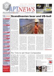
Rio Tinto announces huge write-down of aluminium assets<br />
Mining giant Rio Tinto has revealed a near<br />
USD14 billion (after tax) write-down of its<br />
coal and aluminium assets. The write-down of<br />
the aluminium assets (mainly related to Rio<br />
Tinto Alcan but also to Pacific Aluminium) is<br />
in the range of USD10-11 billion; a further<br />
USD3 billion write-down relates to Rio Tinto<br />
Coal Mozambique. The final figures will be<br />
included in Rio Tinto’s 2012 full year results<br />
due on 14 February.<br />
As a direct consequence of this dramatic<br />
cut, Tom Albanese has stepped down as chief<br />
executive. Iron Ore chief executive Sam<br />
Walsh has been appointed as his successor<br />
with immediate effect.<br />
Chairman Jan du Plessis commented: “The<br />
Rio Tinto board fully acknowledges that a<br />
write-down of this scale in relation to the relatively<br />
recent Mozambique acquisition is unacceptable.<br />
We are also deeply disappointed to<br />
have to take a further substantial write-down<br />
in our aluminium businesses, albeit in an industry<br />
that continues to experience significant<br />
adverse changes globally.” Mr Plessis said<br />
Rio Tinto will implement an “aggressive cost<br />
reduction plan” to improve the company’s<br />
competitive position.<br />
Already at its investor seminar in Sydney<br />
at the end of November, Rio Tinto said that<br />
the annual year-end review of asset carrying<br />
values would most likely result in further<br />
revisions to the value of assets, notably aluminium.<br />
The further deterioration in aluminium<br />
market conditions in 2012, together<br />
with strong currencies in certain regions and<br />
high energy and raw material costs, has had<br />
a negative impact on the current market values<br />
in the aluminium industry.<br />
Rio Tinto acquired Canadian aluminium<br />
flagship Alcan in 2007. The takeover price of<br />
USD101 a share corresponded to some ten<br />
times Rio Tinto’s Ebitda. The mining company<br />
has now written down USD28-29 billion or<br />
about three quarters of the USD38 billion<br />
paid for Alcan.<br />
<strong><strong>ALU</strong>MINIUM</strong> · 1-2/2013 9
WIRTSCHAFT<br />
<br />
<br />
<br />
<br />
<br />
<br />
<br />
<br />
<br />
<br />
<br />
<br />
<br />
<br />
<br />
<br />
<br />
<br />
<br />
<br />
<br />
<br />
<br />
<br />
<br />
<br />
2004 2005 2006 2007 2008 2009 2010 2011 2012<br />
0<br />
50<br />
<strong>–</strong>50<br />
<br />
2.500<br />
<br />
<br />
<br />
<br />
<br />
<br />
2004 2005 2006 2007 2008 2009 2010 2011 2012<br />
2.000<br />
1.500<br />
1.000<br />
<br />
<br />
<br />
<br />
<br />
<br />
<br />
<br />
2004 2005 2006 2007 2008 2009 2010 2011 2012<br />
6.000<br />
5.000<br />
4.000<br />
3.000<br />
2.000<br />
1.000<br />
0<br />
<br />
<br />
10 <strong><strong>ALU</strong>MINIUM</strong> · 1-2/2013
WIRTSCHAFT<br />
Produktionsdaten der deutschen Aluminiumindustrie<br />
Primäraluminium Sekundäraluminium Walzprodukte > 0,2 mm Press- & Ziehprodukte**<br />
Produktion<br />
(in 1.000 t)<br />
+/-<br />
in % *<br />
Produktion<br />
(in 1.000 t)<br />
+/-<br />
in % *<br />
Produktion<br />
(in 1.000 t)<br />
+/-<br />
in % *<br />
Produktion<br />
(in 1.000 t)<br />
Nov 35,2 -1,9 57,0 8,5 152,8 -3,5 53,2 4,7<br />
Dez 35,9 -3,5 46,7 12,1 109,2 -11,5 30,2 -3,5<br />
Jan 12 35,3 -4,7 54,1 7,2 145,4 -6,1 46,3 3,3<br />
Feb 32,4 -4,1 55,6 2,6 149,3 -7,3 47,7 0,9<br />
Mär 34,1 -8,0 57,2 -2,2 165,9 -4,5 50,4 -5,1<br />
Apr 33,5 -6,1 53,3 0,2 147,2 -6,0 45,0 -4,9<br />
+/-<br />
in % *<br />
Mai 34,4 -7,4 54,3 -4,1 160,7 -4,5 48,9 -12,7<br />
Juni 33,0 -8,0 54,6 6,9 161,0 20,6 49,1 -0,3<br />
Juli 34,8 -5,0 56,0 7,1 166,4 0,9 46,9 -7,4<br />
Aug 34,9 -5,8 47,2 2,9 161,4 1,2 44,9 -11,8<br />
Sep 33,6 -4,4 52,5 -4,3 164,5 8,1 44,6 -17,2<br />
Okt 35,2 -2,5 53,3 -0,3 162,5 9,4 46,1 -7,4<br />
Nov 34,2 -2,9 53,4 -6,4 152,9 0,1 42,5 -20,1<br />
* gegenüber dem Vorjahresmonat, ** Stangen, Profile, Rohre; Mitteilung des Gesamtverbandes der Aluminiumindustrie (GDA), Düsseldorf<br />
Primäraluminium<br />
Sekundäraluminium<br />
Walzprodukte > 0,2 mm<br />
Press- und Ziehprodukte<br />
12 <strong><strong>ALU</strong>MINIUM</strong> · 1-2/2013
ECONOMICS<br />
Five hundred participants at Arabal 2012 Conference<br />
© Arabal<br />
Almost 500 participants <strong>–</strong> a record<br />
number <strong>–</strong> attended the Arabal 2012 Conference<br />
in Doha in November last year.<br />
In his opening address to the plenary session<br />
Mohammad Ali Al Naqi, chairman of<br />
the Organising Committee, outlined how<br />
things have changed since the first Arab<br />
Aluminium Conference in 1983. “Today,<br />
as we celebrate the 16 th occasion of<br />
Arabal, the region has seven primary aluminium<br />
smelters with a capacity of up to<br />
15 percent of global production,” he said,<br />
adding that this went along with other,<br />
supporting projects such as calcined coal<br />
and projects that depend on smelters’<br />
products, like aluminium extrusion, cables<br />
and car-wheel factories which supply<br />
the global automotive industry. 1<br />
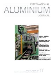
Well attended <strong>–</strong> the Arabal 2012 Conference<br />
The first day of the conference focused on<br />
regional issues, power generation and technology.<br />
Abdulrahman Ahmed Al Shaibi, chairman<br />
of Qatalum, the organising host of Arabal<br />
2012, took the audience through the steps<br />
that the company has taken in Qatar and the<br />
achievements realised in the aluminium industry<br />
and industrial sector. Despite the current<br />
global economic slowdown, he is optimistic<br />
about future development in the aluminium<br />
industry: “We do not expect low prices to<br />
last; unlike many other metals, growth in aluminium<br />
demand is positive and we expect it<br />
to continue,” he said, being confident that the<br />
aluminium price will follow bullish demand<br />
forecasts.<br />
The industrial sector in Qatar was moving<br />
1<br />
Note from the editor: the 15% figure does not<br />
include the Alcoa Ma’aden smelter, which was<br />
inaugurated in mid-December 2012.<br />
on the right track, he noted, “supported by<br />
incentives and industrial benefits that aim to<br />
encourage industrial investment and to focus<br />
on industrial projects that are based on best<br />
available technology”, something which can<br />
no longer be considered on a solely national<br />
basis. “It is truly an international industry,<br />
due to the interdependence between production<br />
and raw material hubs, the smelting and<br />
refining centres and the manufacturing industries,”<br />
he said.<br />
Mr Al Shaibi, who also spoke on behalf of<br />
Mr Al Sada, Minister of Energy and Industry,<br />
pointed out that the aluminium industry<br />
was in a state of restructuring. The economic<br />
downslide in Europe coupled with escalating<br />
power tariffs, lack of local resources, taxation<br />
and tightening of ecological regulations had<br />
already resulted in the shutdown of European<br />
aluminium smelters. “We are seeing a spate<br />
of evolution and consolidation within the<br />
industry. The focus of the aluminium sector<br />
is steadily shifting, often<br />
away from those who were<br />
considered the traditional<br />
leaders. Middle-Eastern<br />
manufacturers are now<br />
increasingly emerging as<br />
serious contenders in the<br />
global aluminium market,”<br />
he said.<br />
Qatalum CEO Tom<br />
Petter Johansen ruled<br />
out direct involvement in<br />
downstream industries but<br />
said the company’s focus<br />
would be on capacity enhancement.<br />
Qatalum smelter tour<br />
Mr Al Shaibi (left) and Mr Al Naqi<br />
Attendees of the conference had the opportunity<br />
to visit the Qatalum smelter at Mesaieed<br />
Industrial City. The 40-minute tour of the<br />
facility <strong>–</strong> which consumes up to one third of<br />
Qatar’s total power usage <strong>–</strong> started at Potline<br />
2, then moved to the baking furnace, paste<br />
plant and anode rodding shop and also to the<br />
casthouse and power plant and to a building<br />
characterised by zero net energy consumption<br />
and zero carbon emissions.<br />
At the paste plant ingredients are mixed to<br />
create new (green) anodes. The baking plant<br />
consists of furnaces where green anodes are<br />
baked to form the black anodes used in the<br />
reduction pots for making liquid aluminium.<br />
The 1,350 MW power plant includes the turbine<br />
building, seawater cooling towers, four<br />
heat recovery steam generators for recycling<br />
exhaust gases and finally the gas insulated<br />
switchgear (GIS) <strong>–</strong> the connection between<br />
the power plant and the smelter. The delegates<br />
were accompanied by tour guides from<br />
Qatalum to answer any questions on the plant,<br />
processes and people.<br />
The role of China<br />
China’s aluminium industry was a major topic<br />
on the final day of the Arabal conference.<br />
Paul Adkins, director of AZ China Limited,<br />
and Eric Zhang, analyst at SMM, spoke<br />
about the peculiarities of the Chinese industry,<br />
which persists with enormous production<br />
despite heavily subsidised losses, at least in<br />
certain provinces. According to Adkins, China<br />
is in the top quartile of the global cost curve.<br />
Its industry consumes scarce energy resources,<br />
is forced to import raw materials and jeopardises<br />
environmental integrity, yet 10 million<br />
tonnes of new capacity are still to come<br />
online.<br />
“Why on earth do the Chinese persist with<br />
making aluminium,” he asked rhetorically. His<br />
answer: “As Westerners and as analysts and<br />
corporates, we focus on the markets, the industry,<br />
equities, P & L (profit & loss), capital<br />
flows, ROI, etc. But by doing so, we can miss<br />
the key point: for the Chinese Communist<br />
Party, aluminium is an important conduit for<br />
the development, urbanisation and modernisation<br />
of China,” he said.<br />
Eric Zhang forecast that domestic aluminium<br />
prices will face many uncertainties in<br />
2013 and are subject to LME aluminium<br />
prices to a large extent. SMM expects domestic<br />
aluminium prices to fluctuate between<br />
RMB15,000-17,500/t (USD2,400-2,800/t) in<br />
2013.<br />
The role of China was a theme carried into<br />
the next session, with a presentation by Jorge<br />
14 <strong><strong>ALU</strong>MINIUM</strong> · 1-2/2013
ECONOMICS<br />
Vazquez, managing director of Harbor Aluminium<br />
Intelligence, who spoke to delegates<br />
on who is winning and losing in the global<br />
aluminium industry and supply chain today.<br />
“Who is getting the value?” he asked. “It is<br />
not the producer for sure.” Today, consumers<br />
are getting the greatest value ever, with<br />
real LME aluminium prices at a cycle bottom<br />
below USD2,000/t, compared to the historical<br />
average of USD2,650/t and a high of about<br />
USD4,700/t.<br />
In his view there are two main sources of<br />
growth in the next five years: emerging Asia<br />
(including the Gulf) and the Americas. Over<br />
16 million tonnes of new aluminium capacity<br />
should hit the market by 2015, two thirds of<br />
this in China for domestic consumption. The<br />
Middle East too is well placed. “We see the<br />
Middle East as the leading provider for growing<br />
world metal needs ahead and the Americas<br />
/ Europe / South East Asia as increasing<br />
import players,” he said.<br />
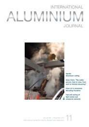
Outlook of the automobile industry<br />
David Cutting, director of J. D. Power Automotive<br />
Forecasting, spoke about the Global<br />
Light Vehicle Market, which is heavily depend-<br />
ent on aluminium.<br />
The global light vehicle<br />
market is predicted<br />
to break through<br />
the 100 million barrier<br />
by 2015, almost<br />
doubling in volume<br />
since the end of the<br />
1990s. Emerging markets,<br />
led by China,<br />
India, Brazil and Russia,<br />
have driven much<br />
of the recent growth<br />
and are expected to<br />
remain key motivators<br />
of future growth.<br />
Light vehicle production<br />
growth in Asia is expected to significantly<br />
outpace the other regions (with share of output<br />
increasing from 48% in 2011 to 53% by<br />
2016).<br />
Shambhu Prasad, senior expert at Gulf<br />
Organisation for Industrial Consulting, noted<br />
that aluminium usage has increased to 140 kg<br />
per car in 2011 <strong>–</strong> predominantly in the drivetrain,<br />
chassis and suspension, and body. The<br />
automotive industry is the largest market for<br />
aluminium castings, which account for more<br />
Qatalum smelter at Mesaieed Industrial City<br />
than 50% of aluminium used in cars.<br />
The day and the conference as a whole<br />
wrapped up with a Culture Night at Skeikh<br />
Faisal Bin Qassim al Thani Museum, with a<br />
tour of the museum followed by a dinner at<br />
Majlis hall, at which delegates could discuss<br />
the connections made, information shared<br />
and arguments put forward over three days<br />
of discussion about the aluminium industry at<br />
national, regional and international level.<br />
<br />
© Qatalum<br />
Dubal’s DX+ technology selected by Alba<br />
Dubai Aluminium has signed an agreement<br />
with Aluminium Bahrain whereby the latter will<br />
use Dubal’s DX+ technology for Alba’s Potline<br />
6 Bankable Feasibility Study. Tim Murray, chief<br />
executive of Alba, pointed out that study would<br />
determine the viability of Alba’s sixth potline expansion<br />
project, which will boost the company’s<br />
aluminium production capacity by approximately<br />
400,000 tpy to 1.280 million tonnes.<br />
Dubals’s DX+ technology is an enhanced version<br />
of Dubal’s proven DX technology. DX+ is<br />
designed to operate at higher amperages and<br />
optimised performance levels. Five DX+ cells, built<br />
in a pilot line at Dubal’s Jebel Ali site in 2010,<br />
initially operated at 420 kA and currently operate<br />
stably at 440 kA. At this level, the DX+ cells yield<br />
substantially better energy efficiency and specific<br />
energy consumption levels than DX cells, and<br />
produce 3,37 tonnes of aluminium per pot per<br />
day. Ultimately, DX+ cells are expected to operate<br />
at 460 kA.<br />
While in the UAE, the Alba delegation visited<br />
Dubal’s Potline 8 <strong>–</strong> a dedicated 40-cell potline<br />
within the greater smelter operations where<br />
Dubal’s proprietary, in-house developed DX technology<br />
has been fully operational since February<br />
2008, and visited Dubal’s DX+ pilot section. The<br />
Alba delegates were also accompanied on a tour<br />
of Emal in Al Taweelah, Abu Dhabi, where 756<br />
DX technology cells, arranged in two potlines,<br />
have been fully operational at Emal Phase I since<br />
the end of December 2010.<br />
“Dubal’s reduction technologies have<br />
been designed fully-modelled and extensively<br />
tested. The results consistently<br />
confirm that both DX and DX+ technology<br />
operate stably, demonstrating not only<br />
the robustness of their design but also the<br />
suitability of both to the Gulf climate,” said<br />
Abdulla Kalban, president and chief executive<br />
of Dubal. “We are delighted that Alba<br />
has recognised these qualities as evidenced<br />
by the selection of DX+ technology for the<br />
Line 6 Bankable Feasibility Study.”<br />
Bechtel to conduct feasibility study<br />
Alba has awarded Bechtel Canada a letter<br />
of intent to conduct the feasibility study<br />
for Potline 6. The study will include the<br />
economic analysis for the construction of a new<br />
Power Station 5. Bechtel has considerable industry-specific<br />
experience in the region and was previously<br />
the EPCM contractor for the Alba Potline<br />
4 and 5 expansions. The study is expected to be<br />
complete by the third quarter of 2013.<br />
View of the Alba site<br />
© Alba<br />
<strong><strong>ALU</strong>MINIUM</strong> · 1-2/2013 15
<strong><strong>ALU</strong>MINIUM</strong> SMELTING INDUSTRY<br />
TMS2013 offers a diversity of light metals<br />
programming and networking opportunities<br />
The Minerals, Metals & Materials Society (TMS) 142 nd Annual Meeting and<br />
Exhibition will take place from 3 to 7 March 2013 in San Antonio, Texas, USA<br />
“This is where the many facets of TMS<br />
meet,” says Wolfgang Schneider, 2012<br />
TMS President and head of the Hydro<br />
R&D Centre in Germany, of the TMS2013<br />
Annual Meeting and Exhibition. “It is at<br />
the core of what we do as a professional<br />
society and showcases the very best of<br />
what TMS has to offer <strong>–</strong> as well as the<br />
very best of what materials science and<br />
engineering has to offer the world.”<br />
processing and production topics pertinent to<br />
the aluminium community are incorporated<br />
throughout TMS2013’s other technical subject<br />
areas. These include: Advanced Characterisation,<br />
Modelling, and Performance; High<br />
TMS2013 Exhibition: Find the expertise and<br />
technology necessary to implement the new<br />
concepts and approaches covered in the<br />
TMS2013 symposia sessions at the three-day<br />
exhibition. TMS will offer a free buffet lunch<br />
The foundation of TMS2013 is an exceptionally<br />
strong technical programme featuring<br />
more than 330 sessions built from more than<br />
3,000 abstract submissions. Topics span the<br />
continuum of materials science and engineering,<br />
from basic research of novel materials to<br />
optimisation of manufacturing processes. This<br />
breadth of programming offers attendees a<br />
unique opportunity to network and learn from<br />
colleagues representing other disciplines, facilitating<br />
the transition of material innovations<br />
from bold idea to successful product.<br />
Contributing to the strength of TMS’s annual<br />
meeting programming is the ‘globalisation’<br />
of contributing authors in recent years.<br />
For TMS2013, nearly half of the abstracts accepted<br />
came from outside the United States.<br />
“The TMS Annual Meeting has evolved into a<br />
truly international event,” he says. “Not only<br />
does this build the prestige of the conference,<br />
but also greatly enhances the depth and quality<br />
of the learning and perspectives that are<br />
gained from attending it.”<br />
TMS2013 highlights of particular interest<br />
to the aluminium industry include:<br />
Technical track devoted exclusively to<br />
light metals: Representatives from the world’s<br />
largest light metals companies and research<br />
organisations convene to discuss breaking<br />
developments, evolving challenges, and new<br />
opportunities. Planned symposia specific to<br />
the aluminium industry include: Aluminium<br />
Alloys <strong>–</strong> Fabrication, Characterisation and Applications;<br />
Alumina and Bauxite; Aluminium<br />
Processing; Aluminium Reduction Technology;<br />
Cast Shop for Aluminium Production;<br />
Deformation, Damage, and Fracture of Light<br />
Metals and Alloys; Electrode Technology for<br />
Aluminium Production.<br />
Interdisciplinary learning opportunities:<br />
Energy management, recycling, and materials<br />
View looking into the exhibition hall at TMS2012<br />
Performance Materials; Materials Processing<br />
and Production; and REWAS 2013: Enabling<br />
Materials Resource and Sustainability.<br />
Aluminium Keynote Session: The TMS<br />
2013 Aluminium Keynote Session will assemble<br />
experts representing a range of perspectives<br />
on managing impurities in the aluminium<br />
supply chain. “The primary goal is to bring<br />
people together from the bauxite / alumina,<br />
reduction, electrode, and casthouse areas to<br />
make the point that we need to think about<br />
impurities holistically rather than something<br />
that affects each area separately,” says Les<br />
Edwards, vice president of Technical Services,<br />
Rain CII Carbon, and session chair. “Taking<br />
this approach can change the way we develop<br />
solutions to impurity problems.” Technical papers<br />
presented in the session will be published<br />
in the 2013 Light Metals proceedings.<br />
Light Metals Division Luncheon: This<br />
popular networking event will feature John<br />
Mitchell, president of Rockwood Lithium<br />
North America, as its featured speaker.<br />
in the exhibition hall on 5 March, along with<br />
the president’s Reception and Happy Hour<br />
Tuesday event. Lunch items will also be available<br />
on 4 and 6 March, to make exhibition<br />
browsing convenient between sessions.<br />
Essential Readings in Light Metals: Available<br />
for sale at TMS2013 will be the just-released<br />
Essential Readings in Light Metals, a<br />
comprehensive collection of the most significant<br />
papers published in the more than four<br />
decades of the Light Metals proceedings. A<br />
rigorous review process, based on a specific<br />
selection criteria, has compiled about 10-15%<br />
of all Light Metals articles into four volumes,<br />
which can be purchased individually or as a<br />
set. Volume topics are: Alumina and Bauxite;<br />
Aluminium Reduction Technology; Cast Shop<br />
for Aluminium Production; and Electrode<br />
Technology for Aluminium Production.<br />
For additional information on TMS2013<br />
and to make registration and housing arrangements,<br />
visit the conference website at<br />
www.tms.org/tms2013.<br />
<br />
© TMS<br />
16 <strong><strong>ALU</strong>MINIUM</strong> · 1-2/2013
<strong><strong>ALU</strong>MINIUM</strong> SMELTING INDUSTRY<br />
Recent development of Dubal<br />
aluminium reduction cell technologies<br />
M. Reverdy, Dubal<br />
Dubai Aluminium (Dubal) commenced<br />
operation in 1979 with a capacity of<br />
90,000 tonnes a year, and it has progressively<br />
grown to reach over one million<br />
tonnes in 2010, predominantly using its<br />
in-house developed D18, D20, CD20,<br />
DX, DX+ and D18+ cell technologies.<br />
The number of reduction cells and the<br />
annual production capacity of these technologies<br />
is shown in Table 1. Recent development<br />
and results of DX+ and D18+<br />
cell technologies will be described in this<br />
paper.<br />
DX cell technology started in 2005 with five<br />
prototype cells, followed by a 40-cell demonstration<br />
potline at Dubal in 2008. The implementation<br />
on a large industrial scale was at<br />
Emal Phase 1 with two potlines and an initial<br />
production capacity of 750 000 tonnes a year<br />
DX cells have operated at 385 kA at Dubal<br />
since March 2012, and at 380 kA at Emal<br />
since September 2012 [1-3]. Five DX+ cells<br />
were started in July 2010 at Dubal at 420 kA<br />
and are now operating at 440 kA. One potline<br />
of 444 DX+ cells is currently under construction<br />
at Emal Phase 2. These cells should start<br />
production in 2013/14 at 440 kA, and they<br />
are designed for a future potential of 460 kA.<br />
D18 cells were recently completely redesigned<br />
for 210 kA and low energy consumption, resulting<br />
in seven D18+ pilot cells. These started<br />
up in March 2012 at 200 kA because there is<br />
no booster for this group of cells.<br />
DX+ cell technology<br />
DX+ cell technology is an evolution of the DX<br />
technology for high productivity and lower<br />
capital cost per installed tonne of capacity<br />
[4-5]. Five DX+<br />
demonstration<br />
cells in Dubal<br />
Eagle Section<br />
are shown in<br />
Fig. 1. The key<br />
performance indicators<br />
(KPIs)<br />
are given in Table<br />
2.<br />
DX+ cells were designed utilising in-house,<br />
commercial software-based mathematical<br />
models that were developed in recent years at<br />
Dubal. These comprise thermo-electric, magnetohydrodynamics<br />
(MHD), mechanical, cell<br />
gas exhaust and potroom ventilation models.<br />
The models were originally validated on operational<br />
DX cells and were re-confirmed on<br />
operational DX+ cells [6]. The alignment between<br />
the models and measurements is excellent,<br />
instilling confidence to use these models<br />
for further optimisation and development of<br />
Dubal cell technologies.<br />
In addition to increased amperage and<br />
higher metal production per day, DX+ tech-<br />
Reduction cell technology Amperage (kA) Number of cells Capacity (kt/y)<br />
D18 202 513 284<br />
D18+ 202 7 4<br />
CD20 250 480 335<br />
D20 249 528 367<br />
DX 385 40 43<br />
DX+ 440 5 6<br />
Total 1,573 1,039<br />
Table 1: Cell technologies at Dubal<br />
Fig. 1: Five prototype DX+ cells in the demonstration section at Dubal<br />
© Dubal<br />
18 <strong><strong>ALU</strong>MINIUM</strong> · 1-2/2013
ANO<strong>DE</strong> BAKING FACILITIES<br />
The Riedhammer anode baking facility is a key<br />
component in a modern anode production plant.<br />
Our plants offer many advantages such as:<br />
• Customised design<br />
• Excellent anode quality<br />
• Extended furnace lifetime<br />
• Low energy consumption<br />
• High productivity<br />
• Flexible equipment supply<br />
• Safe operation<br />
RIEDHAMMER<br />
CARBON BAKING TECHNOLOGY<br />
<br />
<br />
RIEDHAMMER GmbH<br />
Klingenhofstraße 72<br />
90411 Nürnberg<br />
Phone: +49 911 5218 0<br />
Fax: +49 911 5218 231<br />
www.riedhammer.de
<strong><strong>ALU</strong>MINIUM</strong> SMELTING INDUSTRY<br />
KPI<br />
Unit<br />
Dec 2010<br />
to<br />
July 2011<br />
Aug 2011<br />
to<br />
Feb 2012<br />
Mar 2012<br />
to<br />
Sept 2012<br />
1 Oct 2012<br />
to<br />
21 Nov 2012<br />
Amperage kA 419.6 430.2 439.7 440.1<br />
Current efficiency % 95.1 94.9 94.5 94.9<br />
Metal production kg/pot-day 3214 3291 3345 3366<br />
Volts per cell V 4.22* 4.22** 4.24*** 4.24***<br />
DC specific energy kWh/kg Al 13.22* 13.25** 13.37*** 13.37***<br />
Net carbon consumption kg/kg Al 407 412 404 0.398<br />
Fe % 0.040 0.039 0.043 0.036<br />
Si % 0.028 0.029 0.028 0.026<br />
AE frequency AE/pot-day 0.191 0.085 0.071 0.046<br />
AE duration s 9.6 10.3 10.1 10.3<br />
PFC emissions,<br />
CO 2 equivalent****<br />
kg/t Al 33 16 13 9<br />
Fig. 2, above: Historical data on HMI<br />
Fig. 3, below: Pot voltage trend graph on HMI<br />
Table 2: KPIs of Dubal DX+ technology <strong>–</strong><br />
average of the five cells<br />
*Based on 4.35 V actual minus 0.13 V for design changes in<br />
the industrial version of DX+<br />
**Based on 4.32 V actual minus 0.10 V for design changes<br />
in the industrial version of DX+<br />
***Based on 4.31 V actual minus 0.07 V for design changes<br />
in the industrial version of DX+<br />
****CO 2 equivalent is calculated as in Reference [4], using<br />
the Tier 2 method<br />
nology has been optimised in many other ways<br />
with respect to its sister DX technology. In spite<br />
of increased length and width, the mass of the<br />
DX+ optimised potshell was reduced by 21%<br />
without any reduction in strength, thanks to improved<br />
structural characteristics of the design.<br />
The cell superstructure height was lowered by<br />
more than 400 mm, and in spite of its increased<br />
size, its mass was decreased by 12%. The overall<br />
volume of the concrete in the potshell and busbar<br />
supports was reduced by 35%.<br />
Considering the amperage increase to 440<br />
kA, the productivity of potroom in tonnes of aluminium<br />
per square metre of covered building has<br />
increased by 16% to 7.12 tonnes of aluminium<br />
produced per square metre of covered building,<br />
calculated for 360 cells and one central passage<br />
per potroom. Capex improvement is the result of<br />
cell productivity, which is proportional to amperage,<br />
and of the higher number of cells per potline<br />
corresponding to the higher rectiformer voltage<br />
of 2,000 V DC. Further optimisation is under way.<br />
The design of DX+ busbars has already been optimised<br />
and the results are: decrease of cell centreline<br />
distance by approx. 5%, reduction of busbar<br />
mass by 20% and reduction of busbar voltage<br />
drop by 26%. Reduced cell-to-cell distance<br />
increases the building productivity by 4.6%.<br />
In Table 1, the actual voltage and the corresponding<br />
specific energy consumption have been<br />
corrected with respect to demonstration cells<br />
to allow for the expected improvements due to<br />
design changes in the industrial DX+ cells to be<br />
installed at Emal Potline 3. These improvements<br />
include larger cross-sections of busbars and cathode<br />
collector bars. A substantial voltage gain has<br />
been obtained with the introduction of four-stub<br />
anodes at the end of 2011 instead of the threestub<br />
anodes previously used. This explains a different<br />
voltage correction for DX+ industrial cells<br />
for the four periods given in Table 2.<br />
Excellent performance has been maintained in<br />
conjunction with amperage increase. As per tradition<br />
at Dubal, the metal purity is excellent in DX<br />
potlines at both Dubal and Emal as well as in DX+<br />
demonstration cells at Dubal: the metal’s low<br />
iron and silicon content did not deteriorate with<br />
amperage increase. Low anode effect frequency<br />
and duration result in very low PFC emissions<br />
(expressed in CO 2 equivalent kg/t Al in Table 1)<br />
which are a benchmark within the industry [7].<br />
20 <strong><strong>ALU</strong>MINIUM</strong> · 1-2/2013
SPECIAL<br />
<strong><strong>ALU</strong>MINIUM</strong> SMELTING INDUSTRY<br />
Dubal has developed its own proprietary<br />
cell control system, comprising microcomputer<br />
based DCCU (Dubal Cell Control Unit)<br />
and cell control software. DCCU has been<br />
progressively installed since 2005 in Dubal<br />
and also in Dubal-licensed smelters, with<br />
1,276 cells equipped as of November 2012.<br />
Recently, a new hardware system, based on<br />
standard PLC (Programmable Logic Controller),<br />
has been developed and installed on the<br />
five DX+ demonstration cells. It has been also<br />
chosen for Emal Phase 2.<br />
Increased Graphical User Interface (GUI)<br />
capabilities provide improved and more complete<br />
information to cell operators than the<br />
original control systems, which were generally<br />
text based and black<br />
and white. The new Human<br />
Machine Interface (HMI) provides<br />
the operators access to<br />
all required supervisory controls,<br />
data entries and information<br />
about the cells in the potroom.<br />
Two sample screen shots<br />
from HMI are shown in Figs 2<br />
and 3. The HMI can also display<br />
various trend graphs for a period<br />
of 30 minutes to 8 hours<br />
(Fig. 3).<br />
The PLC data are sent to<br />
the potline server, where they<br />
are analysed and displayed in<br />
the same way as with DCCU<br />
based control system. Detailed<br />
pot traces and command interface<br />
can be obtained from ‘iPots’<br />
system hosted on a network<br />
server. In addition, user specified<br />
queries can be used in a<br />
new web based Smelter Analytics<br />
platform developed in-house<br />
to provide data in an exportable<br />
format to programs such as MS<br />
Excel. The new ‘iRPMS’ reporting<br />
system, equipped with a web<br />
based interface for ease of navigation,<br />
provides information<br />
to the user from the potlines,<br />
carbon plant, casthouse, etc. as<br />
well as presenting various types<br />
of summary overviews to the<br />
senior management.<br />
D18+ cell technology<br />
The D18 technology is the result<br />
of Dubal development of the<br />
P69 technology first installed<br />
in 360 cells in Dubal in 1979.<br />
Subsequent additions brought<br />
<br />
Busbar configuration<br />
Al 2 O 3 feeding<br />
D18 D18+<br />
End risers<br />
Pseudo point feed converted<br />
from dual centre breaking<br />
Four side risers with<br />
under cell bus<br />
Four point feeders with<br />
bath sensing breakers<br />
AlF 3 feeding 10 kg bags added manually Dedicated AlF 3 feeder<br />
Alumina distribution Via crane hopper Dense phase system<br />
Number of anodes 18 20<br />
Anode beam control Pneumatic Electric<br />
Number of cathode blocks 17 19<br />
Collector bar <strong>–</strong> flexible connection Bolted Welded<br />
Table 3: Comparison between D18 and D18+<br />
<br />
<br />
the total number to the current 520. Further<br />
significant advances in operating performance<br />
are limited mainly by poor magnetohydrodynamic<br />
(MHD) stability, by alumina<br />
and AlF3 feeding control and by high anode<br />
current density. A new cell design, D18+ has<br />
For over 50 years BUSS KE and CP series Kneaders have been<br />
the benchmark for reliable, cost-effective compounding of<br />
anode pastes. Now we go one step further.<br />
<strong><strong>ALU</strong>MINIUM</strong> · 1-2/2013
<strong><strong>ALU</strong>MINIUM</strong> SMELTING INDUSTRY<br />
KPI<br />
Unit<br />
D18+, 1 June<br />
to 21 Nov 2012<br />
D18<br />
Difference<br />
Amperage kA 202 202 0<br />
Current efficiency % 96.0 92.3 3.7<br />
Metal production kg/pot-day 1,562 1,502 60<br />
Volts per cell V 4.08 4.69 -0.61<br />
DC specific energy kWh/kg Al 12.67 15.14 -2.47<br />
Fe % 0.05 0.07 -0.02<br />
Si % 0.02 0.03 -0.01<br />
AE frequency AE/pot-day 0.02 0.44 -0.42<br />
AE duration (V > 8 V) s 32 31 1<br />
PFC emissions,<br />
CO 2 equivalent [4]<br />
kg/ t Al 12 247 -235<br />
Table 4: D18+ and D18 performance comparison. D18+ is average of 5 middle pots<br />
tion from D18 to D18+ cell design. Additionally,<br />
the original potshell was modified to accommodate<br />
two more cathode blocks. Fig. 3<br />
shows the seven test cells. Table 4 gives key<br />
performance indicators. The performance of<br />
the D18+ cells has now exceeded the original<br />
design targets, resulting in significant improvement<br />
over the existing D18 cells. The<br />
test cells are currently being fully evaluated<br />
before implementing throughout Dubal’s<br />
D18 potlines.<br />
Conclusions<br />
DX+ cell technology continues to give excellent<br />
performance with considerable amperage<br />
increase to 440 kA in DX+ pilot cells.<br />
The new DX+ Pot Control System is based<br />
upon standard market PLCs, which give increased<br />
HMI capabilities and ensure easy<br />
maintenance and future development.<br />
The successful test and validation of the<br />
D18+ cell technology has proven that it is<br />
both technically and practically possible to<br />
update and replace the cell technology within<br />
an existing operating potline. Study of the<br />
feasibility and optimal engineering pathway<br />
is currently in progress to enable replacing<br />
the remaining 513 D18 cells with the D18+<br />
technology.<br />
References<br />
Fig. 4: Completed seven D18+ test cells in a D18 potline<br />
been developed to modernise the original<br />
Dubal D18 potlines and to improve their performance<br />
and economic competitiveness [8].<br />
The objectives behind modernising the cells<br />
through new technology are to reduce the<br />
specific energy consumption to below 12.9<br />
kWh/kg Al, reduce the anode effect frequency<br />
to below 0.10 per cell-day and to allow for a<br />
possible further amperage in-crease of 40 kA.<br />
The constraints were: to maintain the same<br />
cell-to-cell centerline<br />
distance and<br />
the same cell<br />
height, to keep<br />
the amperage<br />
availability limits<br />
within the same<br />
rectifiers and to<br />
use the same gas<br />
treatment centre.<br />
Seven D18+<br />
cells were constructed<br />
and successfully<br />
startedup<br />
in March 2012.<br />
Table 3 gives a list<br />
of changes made<br />
during the transi-<br />
[1] Ali Al Zarouni et al., DX Cell Technology Powers<br />
Green Field Expansion, Light Metals 2010, 339-<br />
343.<br />
[2] B.K. Kakkar et al., Commissioning of Emirates<br />
Aluminium Smelter Potlines, Light Metals 2012,<br />
721-726.<br />
[3] Ali Al Zarouni et al., The Successful Implementation<br />
of Dubal DX Technology at Emal, Light Metals<br />
2012, 715-720.<br />
[4] Ali Al Zarouni et al., DX+ an Optimized Version<br />
of DX Technology, Light Metals 2012, 697-702.<br />
[5] M. Reverdy et al., Advancements of Dubal High<br />
Amperage Reduction Cell Technologies, Light Metals<br />
2013.<br />
[6] Abdalla Zarouni et al., Mathematical Model<br />
Validation of Aluminum Electrolysis Cells at Dubal,<br />
Light Metals 2013.<br />
[7] Abdalla Zarouni et al., Achieving Low Greenhouse<br />
Gases Emission with Dubal’s High Amperage<br />
Cell Technology, 19 th International Symposium IC-<br />
SOBA, Belem, Brazil, 25 Oct. to 2 Nov. 2012.<br />
[8] S. Akhmetov et al, D18+: Potline Modernisation<br />
at Dubal, Light Metals 2013.<br />
Author<br />
Michel Reverdy is Technology Transfer manager at<br />
Dubal.<br />
22 <strong><strong>ALU</strong>MINIUM</strong> · 1-2/2013
REGISTRATION IS NOW OPEN FOR TMS 2013<br />
Register Today and Save $100!<br />
<br />
<br />
<br />
<br />
<br />
<br />
<br />
Also featuring...<br />
2013<br />
Enabling Materials<br />
Resource<br />
Sustainability<br />
<br />
<br />
<br />
<br />
<br />
<br />
<br />
<br />
<br />
<br />
<br />
<br />
<br />
<br />
<br />
<br />
<br />
<br />
Register today at www.tms.org/tms2013
<strong><strong>ALU</strong>MINIUM</strong> SMELTING INDUSTRY<br />
The ‘AP Technology’ smelter of the future<br />
The economical, energy efficient and environmentally safe solution for primary aluminium production<br />
S. Fraysse, J.-M. Jolas, F. Charmier and O. Martin, Rio Tinto Alcan<br />
An efficient smelter solution is made up<br />
of many technological buildings blocks.<br />
The degree of interaction between the<br />
blocks is quite high and can be complex.<br />
Rio Tinto Alcan has not only continuously<br />
developed and optimised these blocks;<br />
over the years, it has also developed a<br />
global approach to its smelter solution.<br />
The global approach, code named<br />
Global Smelter Design (GSD), is used to<br />
design the smelter of the future, building<br />
global and coherent solutions based on a<br />
functional and cross-cutting view of the<br />
plant. The approach has been made even<br />
more relevant by new available technologies<br />
and products in fields as varied as<br />
automation, robotics, data processing,<br />
environmental expertise, innovative civil<br />
works and new materials.<br />
Global smelter design builds upon the<br />
first-in-class AP Technology processes<br />
and in particular, reduction cells to optimise<br />
global development of the smelter<br />
solution.<br />
use the same generic cell equipment:<br />
• AP6X cell, the benchmark of cell<br />
productivity<br />
• APXe, operating at low energy<br />
consumption and the benchmark<br />
environmental performance.<br />
These two versions will make it possible to deliver<br />
optimal solutions for greenfield projects<br />
starting in the next few years.<br />
The first APXe cell was started in December<br />
2010 and has already delivered very<br />
promising results: after less than one year of<br />
operation, the 12.3 kWh/kg target has been<br />
achieved with very low fluoride emission and<br />
at particularly low gas suction rates [1].<br />
More ambitious targets are already planned<br />
for the coming months. Some of the innovative<br />
solutions developed on the APXe cell can also<br />
be deployed in existing aluminium smelters<br />
in order to reduce their energy consumption<br />
and environmental footprint.<br />
An industrial demonstration of AP6X<br />
Platform <strong>–</strong> Jonquiere, Quebec: The Rio Tinto<br />
board of directors approved the AP60 Phase<br />
Reduction cells to support the<br />
existing assets optimisation<br />
and the smelters of the future<br />
The team which has supplied technologies to<br />
a large number of aluminium smelter projects<br />
over the last 40 years has had a unique opportunity<br />
to develop and industrialise the best<br />
cells to meet the greatest constraints and challenges.<br />
The technical challenge of low energy: After<br />
125 years of operation, Hall-Héroult process<br />
cell productivity has improved dramatically<br />
through the development of high-amperage<br />
cells. However, improvement in energy efficiency<br />
levelled off after the seventies. In the<br />
coming decades, the challenge of massive demand<br />
for aluminium in an energy-constrained<br />
future calls for the development of low-energy<br />
cell designs.<br />
With the different AP cell platforms, Rio<br />
Tinto Alcan proposes a comprehensive suite<br />
of solutions able to take up this challenge and<br />
to adapt to changing market trends. This offer<br />
is based on two platforms, AP6X-APXe and<br />
AP4X.<br />
AP6X <strong>–</strong> APXe platform: Rio Tinto Alcan<br />
has developed two new cell technologies that<br />
AP Technology cells<br />
AP Technology, sites in operation and under construction<br />
© Rio Tinto Alcan<br />
24 <strong><strong>ALU</strong>MINIUM</strong> · 1-2/2013
<strong><strong>ALU</strong>MINIUM</strong> SMELTING INDUSTRY<br />
AP6X <strong>–</strong> APXe platform<br />
1 project Notice to Proceed on 14 December<br />
2010 following completion of a comprehensive<br />
feasibility and business evaluation study.<br />
The Jonquiere project is to be constructed<br />
in multiple phases to attain a production<br />
level of 460,000 tpy. Phase 1 with a capacity<br />
of 60,000 tpy capacity is the industrial and<br />
commercial demonstration step. The goal is to<br />
demonstrate, with the 38-pot section, a commercial<br />
operating AP6X potroom, with all the<br />
related logistics and operational challenges.<br />
The first metal is planned for February<br />
2013, and full production in May 2013.<br />
This platform allows us not only to continuously<br />
improve the AP6X pot in an industrial<br />
and robust way, but also to develop and validate<br />
other major improvements such as equipment<br />
capabilities, pot oversuction using the<br />
JIBS RTA-patented system, potroom ventilation,<br />
industrial hygiene and environment performances,<br />
and last but not least automation<br />
and improved accuracy of the anode change<br />
and positioning (‘best anode change’).<br />
AP4X platform: The AP4X platform has<br />
been developed according to the two same<br />
Jonquiere project, potroom<br />
streams: high productivity<br />
and low energy.<br />
This platform supports<br />
the retrofit of existing<br />
AP3X potlines, and<br />
is also a solution for<br />
smaller power blocks.<br />
The two development<br />
streams provide an optimised<br />
solution suited<br />
to each client with his<br />
specific constraints.<br />
The first version of<br />
the AP4X Low Energy<br />
has been developed in collaboration with the<br />
Alouette smelter in Canada and the Saint Jean<br />
de Maurienne smelter in France.<br />
In Alouette [2] a two-year test period resulted<br />
in the validation of a brownfield AP4X<br />
Low Energy design capable of world-class environment<br />
performance in terms of gas emission<br />
and cell life. Rio Tinto Alcan is also currently<br />
on its way to validating a 12.4 kWh/kg<br />
AP4X technology by the end of 2013 in the<br />
Saint Jean de Maurienne boosted section.<br />
Global approach to a smelter<br />
The conventional way of designing a smelter is<br />
to consider the smelter as an assembly of process<br />
shops linked by roads and logistics services.<br />
This approach has not drastically changed in<br />
the past decades, as we can see from the layouts<br />
of the plants erected during this period.<br />
If we change our outlook on smelters,<br />
viewing them as global entities, then there are<br />
new opportunities for improvement and cost<br />
reduction. In addition to developing units, we<br />
can deliver an improved global approach. This<br />
new way of working has led not only to disruptive<br />
innovations in the global management<br />
and layout of smelters, but has also allowed<br />
processes to be reviewed from this new viewpoint.<br />
Some of the innovative solutions developed<br />
using this global approach can also be<br />
deployed in existing smelters.<br />
From a sequential to an integrated design:<br />
New reflections and action plans have been<br />
implemented so as to manage a global approach<br />
and to develop the required elements<br />
accordingly. The construction of a global vision<br />
of the smelter with clearly defined goals<br />
has allowed us to challenge the conventional<br />
‘silo’ approach and to combat the existing paradigms.<br />
‘Open innovation’ is also a key pillar in<br />
our approach, including as far as possible, the<br />
technologies and solutions that can be transposed<br />
from other industries or applications.<br />
Global vision is a medium and long-term<br />
vision resulting from the existing goals and<br />
constraints, based on the aluminium industry<br />
context. It is materialised in a holistic highlevel<br />
roadmap, based on an e3 approach: ‘energy<br />
efficiency’, ‘environment’ and ‘economy’,<br />
with a high standard of health and safety. To<br />
support this high level vision together with operational<br />
goals and steps, we developed a multi-generation<br />
plan, giving us previews of the<br />
‘ideal’ new smelter over the coming decades,<br />
and the steps in optimising existing assets.<br />
Our conventional view of the smelter and<br />
how we work were challenged in a variety of<br />
ways. For example, if we compare the cost of<br />
a smelter not shop by shop but per discipline<br />
(concrete, electrical, structural, equipment,<br />
etc.), we can see that the global building and<br />
roads aspect is more expensive than all the<br />
pots put together. Moreover, as this aspect is<br />
not part of specific aluminium know-how, this<br />
part can be improved with ‘open innovation’<br />
and existing technologies and can be developed<br />
quickly. To take the challenge further,<br />
we can also compare some basic smelter data<br />
such as the cubic metre of concrete or the<br />
tonne of metallic structure to benchmark data<br />
in other industries or applications, and then<br />
analyse the gap and the reasons for the gap.<br />
And finally, ‘open innovation’ starts <strong>–</strong> internally.<br />
Integrated teams need not only development<br />
people, but also production, HSE,<br />
projects, engineering, business improvement<br />
and procurement people. Such a team can<br />
give a different approach and allow an efficient<br />
challenge, finally leading to a global buy-in of<br />
all the stakeholders in the chosen solutions.<br />
External ‘open innovation’ can provide not<br />
only technical ideas and solutions, but also<br />
yield new methodologies and ways of working:<br />
26 <strong><strong>ALU</strong>MINIUM</strong> · 1-2/2013
SPECIAL<br />
<strong><strong>ALU</strong>MINIUM</strong> SMELTING INDUSTRY<br />
Lean manufacturing and flows in the smelter:<br />
Over and beyond the long-standing tradition<br />
of numerical simulation and test programs to<br />
optimise and increase the reliability of cells,<br />
there is room for optimisation of the various<br />
flows (materials, pedestrians, vehicles, fluids)<br />
and, consequently, of general layout, safety<br />
and the environmental footprint. With upward<br />
amperage creep and lower energy consumption,<br />
this optimisation becomes a critical factor<br />
in running a smelter in a reliable and qualityoriented<br />
way, and also economically.<br />
Lean manufacturing has given us basic<br />
principles such as ‘one piece <strong>–</strong> one flow’. This<br />
forms a good starting point to develop a flow<br />
management philosophy that delivers the<br />
right quantity at the right place and at the right<br />
time. With this concept, we consider flows in<br />
the smelter as a key activity, thus generating<br />
a virtuous circle. We use the required technologies,<br />
such as process automation, simulation<br />
or data processing, to bring anodes and<br />
liquid metal, for example, in a repeatable and<br />
safe way, to the pots and to the casthouse as<br />
needed. Consequently, on the one hand, we<br />
challenge the size of the different transport<br />
systems and make savings in smelter infrastructures,<br />
while, on the other hand, we increase<br />
process reliability, and show that ‘just<br />
on time’ is a key enabler for process quality<br />
and thus for the environmental footprint.<br />
Moving from environmental solutions considered<br />
as a cost to environmental challenges<br />
seen as opportunities: The traditional way of<br />
thinking is to consider environmental control<br />
equipment or features as necessary costs. The<br />
global environmental function in the typical<br />
smelter accounts for 12% of direct costs. If we<br />
switch to a mindset where these costs are seen<br />
as creating opportunities, if we are ready to<br />
challenge the old paradigms, then some basic<br />
questions are raised:<br />
• Why should creeping of amperage or size<br />
of the cell automatically result in an<br />
increase in gas suction rate?<br />
• Is a FTC dedicated to baking furnaces the<br />
only scrubbing option if we accept to<br />
change the typical smelter layout and<br />
install the baking furnace much closer to<br />
the potrooms?<br />
One way to answer the first question is to<br />
redesign the cell and the suction system with<br />
the goal of reducing specific flowrate by 50%.<br />
If expressed this way, the objective leads to<br />
innovative solutions which, in turn, open out<br />
towards other avenues with respect to energy<br />
recovery and capex reduction, while also improving<br />
environmental performance.<br />
With respect to the second question, existing<br />
experience shows that there are no major<br />
technical barriers<br />
when considering mixing<br />
the baking furnace<br />
gases with cell gases<br />
and so combining<br />
scrubbing in a conventional<br />
GTC, thereby<br />
optimising costs compared<br />
to the standard<br />
layout.<br />
These are only<br />
examples. Low cost<br />
over-suction solutions<br />
are now also becoming<br />
available on the market<br />
[3] and other approaches can be investigated<br />
to improve this business segment.<br />
Conclusion<br />
The aluminium industry is currently facing<br />
increasingly tougher constraints and challenges,<br />
whether we look at energy savings,<br />
environmental footprint or, over and above<br />
all, economic competitiveness. In the coming<br />
years, this industry needs to make tremendous<br />
improvements and to seek new optimisation<br />
methods.<br />
Rio Tinto Alcan is proposing the reference<br />
solution to successfully take up this challenge.<br />
Not only does it possess the best cell platforms<br />
for both new smelters and for existing<br />
assets optimisation, but it also boasts the only<br />
industrial platform of its kind in the world for<br />
testing the most recent cells.<br />
Over and beyond this strong position, Rio<br />
Tinto Alcan is able to integrate its technological<br />
building blocks in a global approach where<br />
the whole smelter is studied from completely<br />
new viewpoints. The AP Technology smelter<br />
of the future is a global and comprehensive answer<br />
to both existing and future challenges.<br />
References<br />
[1] O. Martin, B. Allano,<br />
E. Barrioz, Y. Caratini,<br />
A. Escande and N. Favel,<br />
Low Energy Cell Development<br />
on AP Technology,<br />
Light Metals 2012<br />
pp. 569-574<br />
[2] P. Coursol, J. Coté,<br />
F. Laflamme, P. Thibault,<br />
A. Blais, D. Lavoie and S.<br />
Gosselin, The Transition<br />
Strategy at Alouette Towards<br />
Higher Productivity<br />
with a Lower Energy<br />
Consumption, Light Metals<br />
2012, pp. 591-594.<br />
[3] J.-N. Maltais, M. Meyer,<br />
M. Leduc, G. Girault and<br />
Global Smelter Design, mindset<br />
H. Rollant, Jet Induced Boosted Suction System for<br />
Roof Vent Emission Control: New Developments<br />
and Outlooks, Light Metals 2012, pp. 551-556<br />
Authors<br />
A combined fume and gas treatment centre<br />
Sylvie Fraysse joined the aluminium business ten<br />
years ago, in process and engineering projects management.<br />
She is currently in charge of the Global<br />
Smelter Design project.<br />
Jean-Michel Jolas has 30 years of aluminium business<br />
experience, half spent in various production<br />
and process management responsibilities in smelters,<br />
and half dedicated to Reduction and Environmental<br />
R&D. In his current position, he is managing the Environmental<br />
R&D group and activities for the Rio<br />
Tinto Alcan primary metal business.<br />
In more than 20 years of aluminum business experience,<br />
François Charmier has held various managing<br />
positions in Technology, Project Management<br />
and Execution, and presently in Technology Sales.<br />
In his current position, he is leading the Technology<br />
Transfer of AP60 to the AAR-CT AP60 Smelter<br />
(‘Aluminerie Arvida <strong>–</strong> Centre Technologique<br />
AP60’).<br />
Olivier Martin has 25 years of aluminium business<br />
experience including various international operational<br />
positions in smelters. Since 2005, he is back<br />
in Rio Tinto Alcan Technology group as Senior<br />
Technology Advisor, head of the Cell Development<br />
group.<br />
<strong><strong>ALU</strong>MINIUM</strong> · 1-2/2013 27
<strong><strong>ALU</strong>MINIUM</strong> SMELTING INDUSTRY<br />
Möller direct pot feeding system for<br />
greenfield and brownfield smelters<br />
C. Duwe and T. Letz, FLSmidth Hamburg<br />
FLSmidth is a market-leading supplier<br />
of equipment and services to the global<br />
minerals and cement industries. With<br />
more than 15,000 employees, FLSmidth<br />
is a global company with headquarters in<br />
Denmark and local presence in more than<br />
50 countries including project and technology<br />
centres in Denmark, India, USA and<br />
Germany.<br />
Over the past 130 years FLSmidth has<br />
developed a business culture based on<br />
three fundamental values: competence,<br />
responsibility and cooperation. For the alumina<br />
and bauxite industries the company<br />
offers complete bauxite handling, storage,<br />
crushing, grinding and settling on the red<br />
mud side, as well as conveying and storage<br />
systems on the white side.<br />
Today’s aluminium smelter industry<br />
requires the most economical, reliable and<br />
environmentally friendly systems in each<br />
part of the smelter. The electrolysis cells<br />
(pots) in all modern greenfield smelters are<br />
already or will be equipped with closed<br />
pot feeding systems. Brownfield smelters,<br />
which still mainly use the open type crane<br />
feeding technology, seem more in need of<br />
changes to the closed pot feeding system<br />
after examining modernisation projects.<br />
The Möller direct pot feeding system is<br />
an innovative system that ensures constant<br />
and reliable feeding of secondary (fluorinated)<br />
alumina to each ore bunker of the<br />
electrolysis cell. Since the first installations<br />
at Vereinigte Aluminium Werke (VAW) in<br />
Hamburg, Germany, and at Aluminij Mostar<br />
in Bosnia-Herzegovina, the design has<br />
continuously been improved in order to<br />
fulfill a wide range of requirements. These<br />
improvements include a flexibility for use<br />
in both greenfield and brownfield smelters.<br />
This paper presents the general design<br />
and latest improvements of the Möller<br />
direct pot feeding. This system will be installed<br />
in the Emirates Aluminium (Emal)<br />
Phase 2 greenfield project in Taweelah,<br />
Abu Dhabi, and in a brownfield project at<br />
Alcasa in Venezuela.<br />
General description<br />
The vent air from the electrolysis cells is evacuated<br />
via gas ducts to the Gas Treatment Centres<br />
(GTC) where primary (fresh) alumina absorbs<br />
many of the emissions. During this cleaning<br />
process the primary alumina becomes secondary<br />
alumina and is stored in silos, near the<br />
potrooms respective GTCs.<br />
From the secondary alumina silos the direct<br />
pot feeding system transports the secondary<br />
alumina pneumatically to each of the electrolysis<br />
cells. The fully automatic and absolutely<br />
dust-free feeding process can be either continuous<br />
or discontinuous, and it works independently<br />
from the potroom cranes.<br />
The smooth-working Möller direct pot feeding<br />
system combines the ‘Möller Turbuflow’<br />
dense phase and ‘Möller Fluidflow’ pipe air<br />
slide transport system to take the secondary<br />
alumina from the storage silo to distribution<br />
pieces at the electrolysis cells. From there the<br />
Möller Fluidflow pipe air slide feeding system<br />
takes alumina to each of the ore bunkers of the<br />
electrolysis cells. The Möller Turbuflow dense<br />
phase conveying and the Möller Fluidflow<br />
pipe air slide are both well proven transport<br />
technologies which have established itself because<br />
of its superior performance record.<br />
Highlights of the Möller direct pot feeding<br />
system complete with Möller Fluidflow pipe<br />
air slides are:<br />
• Highest possible performance and reliability<br />
of continuous feeding of the electrolysis<br />
cells for almost all kinds of secondary<br />
Fig. 1: Process flow diagram, Möller direct pot<br />
feeding system complete with Möller Fluidflow<br />
pipe air slides<br />
© FLSmidth Möller<br />
28 <strong><strong>ALU</strong>MINIUM</strong> · 1-2/2013
SPECIAL<br />
<strong><strong>ALU</strong>MINIUM</strong> SMELTING INDUSTRY<br />
or primary alumina qualities by Möller<br />
Fluidflow pipe air slide<br />
• Gas-tight pot feeding system by Möller<br />
Fluidflow pipe air slide (no dust emission<br />
from flange connections)<br />
• No generation of fines, no segregation and<br />
no scaling<br />
• Lowest possible (over-)pressure<br />
• Self-regulating system by filling level in<br />
ore bunkers of cells<br />
• Works independently of any slight overpressure<br />
or slight under-pressure in the<br />
ore bunkers of the electrolysis cell<br />
• Quickest possible (emergency) refilling<br />
of the ore bunkers of the electrolysis cells<br />
by Möller Fluidflow pipe air slides and<br />
high performance fans or blowers<br />
(0.1-0.2 bar)<br />
• Lowest possible emission to GTC gas duct<br />
• No pulsation in the Möller Fluidflow pipe<br />
air slide along the potroom and on top<br />
of each cell<br />
• Independent of the filling level of the<br />
buffer silo<br />
• Minimised energy consumption. Low<br />
fluidising air amount and energy<br />
consumption by use of frequency<br />
controlled fans or blowers<br />
• Minimised maintenance work as well as<br />
minimised amount of spare parts.<br />
Functional description<br />
and design features<br />
Silo discharge including material trap: The<br />
Fig. 2: Möller rotary flow control valve and material trap<br />
secondary alumina is discharged via Möller<br />
rotary flow control valve and Möller Fluidflow<br />
pipe air slide, generally from the secondary<br />
alumina silo at the GTC, and transported to<br />
the so-called main bin.<br />
A specifically designed material trap is<br />
installed to avoid any foreign particles entering<br />
the direct pot feeding system. In greenfield<br />
aluminium smelters, vibrating screens
<strong><strong>ALU</strong>MINIUM</strong> SMELTING INDUSTRY<br />
Fig. 3: Möller Fluidflow pipe air slide from secondary alumina silo to potroom<br />
wall; main bin and Möller Fluidflow pipe air slide along potroom (Dubal)<br />
in the GTC system already remove most<br />
of the coarse material (e. g. from scaling effects).<br />
However, in brownfield aluminium<br />
smelters the existing installation situation<br />
may not have enough space in which to install<br />
vibrating screens. To address this, FLSmidth<br />
enhanced the design of the material trap in<br />
order to include the process function of a<br />
vibrating screen. The Möller direct pot feeding<br />
system can generally be installed at every<br />
brownfield smelter presently operating with a<br />
crane feeding system.<br />
Main bin: The main bins <strong>–</strong> normally one<br />
main bin is used for each half of a potroom <strong>–</strong><br />
are located right next to the potroom wall.<br />
The main bins are always 100% filled, and<br />
the resulting material column ensures a continuous<br />
mass flow of secondary alumina to all<br />
electrolysis cells, e<strong>special</strong>ly to the last cell at<br />
the end of the Möller Fluidflow pipe air slide<br />
along the potroom.<br />
Because of the well-defined height of the<br />
main bin, the Möller direct pot feeding system<br />
is independent of the filling level of the secondary<br />
alumina silo. Whether the secondary<br />
alumina silo is full, half full or nearly empty,<br />
the conveying capacity of the Möller direct pot<br />
feeding system stays<br />
the same.<br />
Given the sufficient height between the<br />
outlet flange of an existing secondary alumina<br />
silo and the superstructure of the electrolysis<br />
cell, then the Möller Fluidflow pipe air slide<br />
can also be installed along the potroom with<br />
an appropriate declination (downhill slope)<br />
without a main bin.<br />
Distribution pieces and vent domes: From<br />
the main Möller Fluidflow pipe air slide along<br />
the potroom the secondary alumina is transported<br />
via the distribution pieces into the<br />
potroom, and then to the electrolysis cells.<br />
According to the design requirements, a sufficient<br />
number of vent domes will be installed<br />
on top of the distribution pieces. All necessary<br />
venting domes are connected to the gas duct<br />
of the GTC.<br />
Each of the above described distribution<br />
pieces can be connected to one (single-feed),<br />
two (double-feed) or even more electrolysis<br />
cells (multi-feed), as per customer requirements<br />
resp. installation situation.<br />
Superstructure design requirements: Each<br />
superstructure is <strong>special</strong>ly designed as part of<br />
the electrolysis cell’s technology. Generally,<br />
the state-of-the-art electrolysis cell technologies<br />
already ensure sufficient space for a direct<br />
pot feeding system.<br />
However, clients have<br />
Fig. 4: Möller distribution pieces and vent dome<br />
different requirements regarding free access<br />
for crust breakers, dosing devices and the option<br />
for removing the ore bunkers during operation,<br />
and these factors influence the final<br />
design of the Möller Fluidflow pipe air slide<br />
to be installed on top or inside of the superstructure<br />
of the electrolysis cell.<br />
The self-regulating and continuous filling<br />
process of the ore bunkers of an electrolysis<br />
cell by the Möller direct pot feeding system<br />
is simply ingenious. If the ore bunker is full,<br />
then the material cone level has reached the<br />
filling spout discharge opening of the Möller<br />
Fluidflow pipe air slide, and the mass flow is<br />
blocked automatically. As soon as secondary<br />
alumina is removed from the ore bunker of<br />
the electrolysis cell, the pneumatic transport<br />
starts again automatically and ensures a constant<br />
and reliable mass feed rate to the pots.<br />
The fluidising of the secondary alumina inside<br />
the Möller Fluidflow pipe air slide works permanently<br />
to ensure a constant bulk density.<br />
Fluidisation air equipment: The fluidisation<br />
air requirements for the Möller Fluidflow<br />
pipe air slide along the potroom and on top of<br />
the electrolysis cells are different in regard to<br />
the fluidisation air pressure and the specific<br />
fluidisation air amount. Therefore, the Möller<br />
direct pot feeding system uses two different<br />
fluidisation air sources which can either be<br />
frequency controlled rotary piston blowers<br />
Fig. 5: Single-feed design …<br />
Fig. 6: … and double-feed design of the Möller direct pot feeding system<br />
30 <strong><strong>ALU</strong>MINIUM</strong> · 1-2/2013
SPECIAL<br />
<strong><strong>ALU</strong>MINIUM</strong> SMELTING INDUSTRY<br />
or fans. This design allows minimised energy<br />
consumption during operation down to the<br />
necessary minimum amount as well as minimised<br />
fluidisation air vented into the GTC’s<br />
gas duct.<br />
Conclusion<br />
Fig. 7: Variable design of the Möller Fluidflow pipe air slide on top or inside<br />
of the electrolysis cell<br />
The necessary flexibility of a closed pot feeding<br />
system to serve greenfield and brownfield<br />
aluminium smelters had already to be considered<br />
by FLSmidth Hamburg when the Möller<br />
direct pot feeding system was introduced at<br />
VAW in Hamburg in 1997, and at Aluminij<br />
Mostar, Bosnia-Herzegovina in 2001. In particular,<br />
the latest contracts for Emal Phase 2,<br />
Abu Dhabi (greenfield), and Alcasa, Venezuela<br />
(brownfield), have proven the system’s high<br />
adaptability with great success.<br />
This system is designed to ensure a constant<br />
and a reliable feed into the ore bunkers<br />
of the electrolysis cells at the highest possible<br />
standard. The lowest<br />
possible conveying<br />
velocities preserve the<br />
particle size distribution<br />
as well as the flow<br />
ability of the secondary<br />
alumina without<br />
any scaling effects.<br />
This most competitive<br />
system is superior by<br />
minimising wear and<br />
maintenance as well as<br />
energy consumption,<br />
and last but not least<br />
Fig. 8: Self-closed filling spout and filling process of<br />
the ore bunker<br />
<strong><strong>ALU</strong>MINIUM</strong> · 1-2/2013 31
<strong><strong>ALU</strong>MINIUM</strong> SMELTING INDUSTRY<br />
Contract Client Smelter Type System description<br />
2001 Aluminij Mostar brownfield<br />
256 pots, 130 kg/h/pot (double-feed),<br />
potroom length 600 m<br />
2006 Dubal, Potline 8 greenfield 40 DX pots, 210 kg/h/pot (double-feed)<br />
2007<br />
2007<br />
2007<br />
IMIDRO, Hormozal<br />
Aluminium Smelter<br />
Rusal/Hydro, Boguchany<br />
Aluminium Smelter<br />
Rusal, Taishet Aluminium<br />
Smelter<br />
greenfield<br />
greenfield<br />
greenfield<br />
2012 Emal, Phase 2 greenfield<br />
2012 CVG Alcasa, Potline 3/4 brownfield<br />
228 D20 pots, 170 kg/h/pot (double-feed),<br />
potroom length 720 m<br />
672 RA300 pots, 200 kg/h/pot (double-feed),<br />
potroom length 1,050 m<br />
672 RA400 pots, 200 kg/h/pot (double-feed),<br />
potroom length 1.050 m<br />
444 DX+ pots, 480 kg/h/pot (single-feed),<br />
potroom length 1,520 m<br />
400 pots, 480 kg/h/pot (single-feed),<br />
potroom length 700 m<br />
Tab. 1: Möller direct pot feeding system references in operation or under construction; all secondary alumina<br />
by its high operating reliability.<br />
In close co-operation with clients around<br />
the world, FLSmidth Hamburg has offered and<br />
contracted various tailor-made solutions for<br />
the use of a Möller direct pot feeding system.<br />
Please contact the authors for more detailed<br />
information or to obtain support regarding<br />
specific projects.<br />
Authors<br />
Dipl.-Ing. Carsten Duwe is head of Technical Department<br />
and Dipl.-Ing. Timo Letz is area sales manager<br />
of FLSmidth Hamburg GmbH, based in Pinneberg,<br />
Germany. Contact: carsten.duwe@flsmidth.<br />
com; timo.letz@flsmidth.com<br />
Cathode producer shows its metal<br />
M. Casasole, Carbone Savoie<br />
© Carbone Savoie<br />
Carbone Savoie’s plant in Notre Dame de Briançon<br />
Aluminium has been one of the mainstays of<br />
industrial production for several decades. It is<br />
one of the most plentiful elements on earth,<br />
and its lightness and strength makes it ideal for<br />
many applications. The production of aluminium<br />
involves electrolysis, and creating increasingly<br />
better technology for the aluminium producers<br />
is the <strong>special</strong>ty of Carbone Savoie.<br />
Carbone Savoie is one of the worldwide<br />
leading manufacturers of cathode products,<br />
the design and production of cathode blocks,<br />
graphitised blocks, sidewall blocks and ramming<br />
paste. The company’s unique graphitised<br />
block has given it a significant competitive<br />
edge over its nearest rivals.<br />
Since 2010, Carbone Savoie provides a<br />
new generation of ramming paste NeO 2 . Unlike<br />
the previous pastes and unlike all other<br />
pastes of the market that contain toxic compounds,<br />
NeO 2 is a 100% clean ramming paste.<br />
This first 100% clean ramming paste contributes<br />
towards huge progress to the aluminium<br />
production, and it guarantees a clean and safe<br />
environment for our customers’ and own employees.<br />
Despite short terms uncertainties, the basis<br />
for aluminium growth remains strong. Ramming<br />
paste, sidewalls and cathode blocks will<br />
be part of this trend.<br />
Success for Carbone Savoie is underpinned<br />
by its excellent reputation. A decisive factor<br />
is the long life of its cathodes. The concern<br />
ploughs a significant part of turnover back into<br />
research and development. Carbone Savoie<br />
sees its clients more as partners than customers,<br />
and so offers consulting and advice<br />
throughout the lifetime of the cathodes which<br />
it supplies. Naturally, in such a technologically<br />
advanced field, R & D is carried out in close<br />
co-operation with technical departments of<br />
universities and other research organisations.<br />
Carbone Savoie’s long-term strategy is to<br />
improve sustainability, and to deliver sales<br />
commitment, as well as to develop both the<br />
The end product, a cathode block, ready for delivery<br />
organisation itself<br />
and to extend<br />
the skills of its<br />
staff. Steps will be<br />
taken to ensure<br />
long-term profitability<br />
by closely<br />
watching aspects<br />
like product mix,<br />
production costs<br />
and pricing mechanisms.<br />
It is our vision<br />
to let our actions NeO 2 : the first 100% clean<br />
be directed by respect<br />
for the environment at all levels. We strive<br />
ramming paste<br />
to remain the commercial and technological<br />
leader in our business fields. We aim to remain<br />
the most reliable company operating in<br />
the market today and to be the manufacturer<br />
of the best products that money can buy. Some<br />
of our profits will continue to be directed back<br />
into research and environmental protection. It<br />
is what our customers expect from us in what<br />
is a constantly changing world.<br />
The company is anticipating and going beyond<br />
expected new regulatory requirements<br />
and is running a project to study further ways<br />
of treating all fumes released by the plant.<br />
With its outlook towards technological<br />
innovation and environmental sustainability,<br />
Carbone Savoie is set for a bright future.<br />
Author<br />
Matthieu Casasole is sales and marketing director<br />
of Carbone Savoie, based in Vénissieux, France.<br />
32 <strong><strong>ALU</strong>MINIUM</strong> · 1-2/2013
SPECIAL<br />
<strong><strong>ALU</strong>MINIUM</strong> SMELTING INDUSTRY<br />
Alumina refinery<br />
Outotec’s process and implementation solution<br />
M. Missalla, A. Scarsella and A Koschnick, Outotec<br />
In retrospect, it is hard to say whether<br />
Austrian chemist Karl Josef Bayer knew<br />
how significant his two patents <strong>–</strong> A process<br />
for the production of aluminium hydroxide<br />
and The pressure leaching of bauxite<br />
with NaOH to obtain sodium aluminate<br />
solution <strong>–</strong> would be for the future alumina<br />
industry when he filed for them in 1888<br />
and 1892 respectively [1]. However, it is<br />
clear that within two years of obtaining his<br />
patents, the first industrial alumina plant<br />
was commissioned in 1894 in Gardanne,<br />
France for Société Française de l’Alumine<br />
Pure. The plant’s capacity, 1.5 tonnes per<br />
day, was very small compared to current<br />
plant capacities: newly implemented alumina<br />
refineries range between 1-2 million<br />
tonnes of alumina per year.<br />
Implementing an entire alumina refinery<br />
In addition to the costs for an alumina refinery,<br />
investments are also needed for various<br />
infrastructures such as railroads, harbours,<br />
roads and villages. Most investors usually<br />
rely on the traditional front end loading (FEL)<br />
methodology for capital project planning. It involves<br />
four phases with a decision gate after<br />
each phase. The order of magnitude, pre-feasibility<br />
and basic engineering phases are commonly<br />
known as FEL 1, 2 and 3, and these<br />
are generally contracted with a technology-independent<br />
engineering contractor. In contrast,<br />
FEL 4, or project implementation, is done with<br />
an EPCM contractor. At first glance, this appears<br />
to be the best implementation model<br />
in terms of low capex costs, since it allows to<br />
combine a variety of sub-process solutions,<br />
and it ensures maximum competition among<br />
the technology/equipment suppliers as well as<br />
among the engineering/EPCM contractors.<br />
However, a quick review of some recent<br />
projects utilising the EPCM model shows that<br />
many of interfaces in these complex projects <strong>–</strong><br />
both from a technological and management<br />
perspective <strong>–</strong> have suffered significant delays<br />
to implementation schedules as well as tremendous<br />
cost overruns. Focussing on separate<br />
process units instead of on a comprehensive<br />
optimised process solution often creates operational<br />
problems, and can transform initially<br />
viable ‘solutions’ into a customer’s ‘problem’.<br />
With an EPCM contract, the absence of a comprehensive<br />
implementation approach and of<br />
Fig. 1: A tradition of demonstrating industrial plant expertise over the last century<br />
process guarantees leads to problems where<br />
customers find themselves having sole liability.<br />
Thus, the EPC/turnkey approach for the<br />
core process area, where competent technology<br />
solution providers are involved at an early<br />
project stage, is increasingly favoured by the<br />
industry where the first projects in alumina<br />
were contracted using this model.<br />
Outotec’s mission is to be a leading provider<br />
for sustainable process life cycle solutions.<br />
Its ability to offer turnkey project implementation<br />
with full implementation and process<br />
guarantees makes the company a preferred<br />
choice for the industry, allowing customers to<br />
focus on their core business.<br />
Providing life-cycle technology process<br />
solutions to the alumina industry<br />
With a track record of successful EPC/turnkey<br />
project implementations going back several<br />
decades, Outotec has a unique value proposition:<br />
it offers integrated engineering, project<br />
and risk management, which aggregates value<br />
to a customer’s investment in terms of<br />
• Optimised, sustainable process solutions<br />
• Guarantees for implementation within<br />
schedule and budget<br />
• Guarantees for final product quality,<br />
capacity and consumption figures<br />
• Best value for investment.<br />
Fig. 2 : The Bayer cycle<br />
© Outotec<br />
<strong><strong>ALU</strong>MINIUM</strong> · 1-2/2013 33
<strong><strong>ALU</strong>MINIUM</strong> SMELTING INDUSTRY<br />
Fig. 3: Alumina refinery layout<br />
With an EPC contract, customers hand over<br />
a significant portion of their investment risks<br />
to the contractor. Outotec has structured its<br />
organisation to control and cope with these<br />
risks: within its technology competence centres,<br />
process and engineering disciplines are<br />
integrated using the latest design tools available.<br />
With a global procurement organisation<br />
and a network of approved manufacturers,<br />
not only does Outotec have access to the most<br />
cost-efficient supply chain, but it also has the<br />
flexibility to react to any surprises which suddenly<br />
appear on the market. Additionally, Outotec’s<br />
project management teams work with<br />
the latest management tools and procedures<br />
for scheduling, cost control, document control<br />
quality and HSE management. But what really<br />
brings excellence to this organisation is Outotec’s<br />
experienced staff <strong>–</strong> with an average age<br />
of 40+, most of the company’s professionals<br />
have at least 15 years of experience in industrial<br />
projects.<br />
Proof of this technology and project execution<br />
excellence is supported by extensive<br />
reference lists of successfully implemented<br />
LSTK contracts and plants operating with<br />
benchmark parameters for productivity and<br />
sustainability.<br />
Fig. 4: Temperature profile of the Bayer circuit<br />
Fig. 5: Autoclave digestion train [2]<br />
The Bayer process<br />
The Bayer process is a highly integrated grinding,<br />
leaching and recovery process. Ground<br />
bauxite is dissolved (digested) at a high temperature<br />
in a highly concentrated solution of<br />
sodium hydroxide more commonly known as<br />
‘caustic’. The next step involves other bauxite<br />
components which do not digest and which<br />
are separated by a thickening and security<br />
filtration step before being washed and then<br />
stored as red mud. The alumina-rich solution<br />
is cooled and the aluminum tri-hydrate is precipitated<br />
from the solution. The alumina-depleted<br />
caustic solution next undergoes evaporation,<br />
so increasing the caustic concentration,<br />
and is recycled back to digestion, thus closing<br />
the Bayer cycle. The aluminum tri-hydrate is<br />
filtered, washed and finally thermally treated<br />
resulting in calcined aluminum oxide as a<br />
product (Fig. 2).<br />
Estimating a refinery’s correct capital is not<br />
restricted to basic tankage, and the budget for<br />
major equipment or civil requirements also includes<br />
interconnecting piping, conveyors and<br />
roads. In addition to the total capital expenditure,<br />
the operational expenditure must also be<br />
clearly understood and optimised during the<br />
designing and implementation of your alumina<br />
refinery. This, in turn, helps determine future<br />
refinery profitability and the payback period.<br />
<br />
34 <strong><strong>ALU</strong>MINIUM</strong> · 1-2/2013
ddilisa@innovatherm.de
<strong><strong>ALU</strong>MINIUM</strong> SMELTING INDUSTRY<br />
Fig. 7: Basic flow<br />
chart for seawater<br />
neutralisation of<br />
red mud [4]<br />
Fig. 6: Tube digestion [3]<br />
It goes without saying that the aim of every<br />
refinery is to become a low-cost producer, and<br />
so must examine the major factors influencing<br />
the first-quartile costs:<br />
• Proximity to the bauxite mine<br />
• Proximity to a deepwater harbour<br />
• Low energy cost<br />
• Low soda cost<br />
• Low energy, caustic and lime<br />
consumptions.<br />
The first four factors depend on the location<br />
selected as well as on available infrastructure.<br />
The final factor depends on the bauxite mineralogy<br />
and on selection of the technology<br />
to be applied. Fig. 4 shows the bauxite entering<br />
the grinding step at ambient temperature,<br />
where it is then mixed with the spent liquor.<br />
The ground suspension is heated to its digestion<br />
temperature, which is determined by the<br />
bauxite’s composition: gibbsitic bauxites need<br />
low temperatures, while boemitic bauxites require<br />
higher temperatures. The digested slurry<br />
is then rapidly cooled and the green liquor<br />
(alumina-rich solution) is separated from the<br />
red mud. In the same figure, heat recovery is<br />
maximised so as to minimise the addition of<br />
live steam needed to bring the fresh slurry to<br />
the required digestion temperature. A similar<br />
principle can be seen when the incoming green<br />
liquor is indirectly cooled with outgoing spent<br />
liquor prior to precipitating alumina tri-hydrate<br />
in the next stage. The hydrate is then fed<br />
to the calcination stage. The figure also makes<br />
it easy to distinguish between the white and<br />
red sides of an alumina refinery production<br />
site.<br />
venture with Hatch <strong>–</strong> HOT (Hatch<br />
Outotec) <strong>–</strong> can supply the entire<br />
digestion tool box. The joint venture focuses<br />
on designing and developing integrated tube<br />
digestion and evaporation solutions using single-stream<br />
heating in jacketed pipe technology.<br />
This allows you to efficiently recover the<br />
heat in the digested slurry. Fig. 6 shows the<br />
slurry as it is heated to the digestion temperature<br />
and then held for a time in tube reactors<br />
to meet the reaction requirements. Next, the<br />
slurry is flash cooled in stages to near- ambient<br />
pressure, while using the heat from vapour to<br />
the pre-heat incoming slurry in counterflow.<br />
The water vapour transfers its heat to the<br />
slurry as it condenses on the outside shell of<br />
the jacketed pipes.<br />
Red mud disposal: sea<br />
water neutralisation<br />
The residue from the Bayer process <strong>–</strong> more<br />
commonly known as red mud <strong>–</strong> still has a<br />
high alkaline content and must be neutralised.<br />
Fig. 7 illustrates the basic flow<br />
chart for neutralisation by magnesium in the<br />
sea water. The mud / seawater mixture is held<br />
in a reactor so that the caustic is chemically<br />
neutralised. The hydrotalcite-rich mud and<br />
magnesium-deficient seawater are then decanted<br />
using a conventional clarifier.<br />
The supernatant magnesium-deficient seawater<br />
with the correct permits is now suitable<br />
for environmental discharge.<br />
The small facility shown in Fig. 8 can treat<br />
the entire rate of red mud production from<br />
a refinery producing four million tonnes of<br />
product per year to environmentally acceptable<br />
levels. The magnesium actively reacts<br />
with the liquor phase components of red mud;<br />
namely aluminum and hydroxide ions. During<br />
the neutralisation process, the dissolved<br />
magnesium levels drop from approx. 1,200<br />
mg/l to around 300 mg/l and the aluminum<br />
level drops to less than 5 mg/l. These net reductions<br />
of magnesium and aluminum are the<br />
Digestion and evaporation<br />
The appropriate equipment for digestion must<br />
be selected based on the kinetics of the digestion<br />
reactions, bauxite type and target heat<br />
recovery. Available technology for the digestion<br />
process includes autoclaves and tube<br />
digestors, which are selected according to<br />
throughput, number and size. Outotec’s joint<br />
Fig. 8: Neutralisation facility [4]<br />
36 <strong><strong>ALU</strong>MINIUM</strong> · 1-2/2013
<strong><strong>ALU</strong>MINIUM</strong> SMELTING INDUSTRY<br />
result of their precipitation as insoluble salts,<br />
forming hydrotalcite as a product.<br />
Calcination<br />
The average energy consumption in the calcination<br />
processes for an alumina refinery<br />
globally exceeds 3,100 kJ/kg of alumina.<br />
Outotec calcination technology has reduced<br />
this figure to about 2,800 kJ/kg of alumina. In<br />
fact, Outotec was recognised with an honourable<br />
mention from the German energy agency<br />
Dena in 2010. Additionally, Outotec can provide<br />
numerous references for its calcination<br />
technology.<br />
Cyclones are an integral component of a<br />
circulating fluidised bed (CFB) calciner and a<br />
key element for efficient heat recovery with a<br />
minimal impact on product quality. The typical<br />
CFB calciner layout includes five cyclones,<br />
each customised to the prevailing process conditions.<br />
The cyclone’s geometry is critical its<br />
performance in terms of separation efficiency<br />
and particle breakage, and thus by extension,<br />
for the overall performance of the calciner.<br />
References<br />
[1] F. Habashi : Bayer’s Process for Alumina Production:<br />
A Historical Perspective, Bull. Hist. Chem.<br />
17/18 (1995), p. 15-19<br />
[2] B. Haneman, A. Wang: Optimising Flash Tank<br />
Design for the Alumina Industry. 9 th Alumina Quality<br />
Workshop (2012) p 127-131<br />
[3] A. Wang, B. Haneman, C. Coleman: Pressure<br />
Surge Mitigation at High Temperature Tube Digestion<br />
Facility of Yarwun Alumina Refinery. 9 th Alumina<br />
Quality Workshop (2012) p 132-137<br />
[4] A. Scarsella, T. Leong, B. Henriksson: A Novel<br />
and Environmentally Friendly Process for the Treatment<br />
of Bayer Process Residue. 9 th Alumina Quality<br />
Workshop (2012) p 171-175<br />
Authors<br />
Michael Missalla heads the Light Metals/Fluidised<br />
Beds business line at Outotec. He has designed<br />
several processes for a variety of metallurgical applications.<br />
His PhD topic was ‘Calculation method<br />
for highly loaded cyclones’. He also has experience<br />
in chemical plant operations, process engineering,<br />
R&D, as well as in training and development.<br />
Alessio Scarsella heads the Alumina Refinery group<br />
at Outotec Germany and has extensive experience<br />
in combustion and alumina refining. He has an MBA<br />
from Deakin University and a PhD in chemical engineering<br />
from the University of Adelaide in fluid<br />
mechanics and combustion. Dr. Scarsella has held<br />
process and senior project leading positions in the<br />
alumina industry, where he developed fundamental<br />
and operational expertise in refining alumina from<br />
bauxite. He has also executed major greenfield refinery<br />
projects.<br />
Andreas Koschnick is Outotec’s director for Solution<br />
Sales Latin America. He holds a degree in industrial<br />
engineering and began his career with Lurgi<br />
in project management for the Leuna petrochemical<br />
refinery, which was the largest industrial project in<br />
Europe. As a former general manager of a construction<br />
and engineering company in Brazil, he was responsible<br />
for the implementation of major industrial<br />
projects in the energy and metallurgical sector.<br />
Fives Solios <strong>–</strong> 30 years of experience in fume desulphurisation<br />
A. Courau, Solios Environnement<br />
Formerly Procedair, Solios Environnement<br />
has supplied turn-key plants for<br />
fume desulphurisation dedicated to many<br />
different industrial applications,<br />
such as diesel motor production,<br />
paper fabrication, sulphuric acid<br />
production, anode baking furnaces,<br />
electrolysis reduction gases,<br />
or waste incineration. Today, Solios<br />
Environnement’s know-how<br />
in desulphurisation processes<br />
mainly applies to electrolysis pot<br />
gases or to anode baking furnace<br />
fumes of primary aluminium<br />
smelters.<br />
Relying on its long-standing experience,<br />
Fives Solios is now a privileged<br />
partner for the design of SO 2<br />
scrubbers. Indeed, after studying all<br />
parameters of a project and evaluating<br />
all available technologies, Solios<br />
Environnement is able to propose<br />
tailor-made solutions in which its<br />
efficient SO 2 units combine various<br />
processes and meet perfectly its customers’<br />
needs.<br />
While projects that are located<br />
near the sea can benefit from using<br />
seawater in wet scrubbers, various<br />
other solutions are available in other<br />
geographic locations. This article reviews all<br />
solutions already considered and exploited for<br />
SO 2 treatment without seawater.<br />
Like many existing technologies, Fives Solios’s<br />
desulphurisation treatments commonly use a<br />
calcium reagent (limestone, lime, lime milk),<br />
Application Process Technical data available<br />
Methionine production for<br />
animal food industry (France)<br />
Desulphurisation on two<br />
diesel engines of 5 MW with<br />
heavy fuel oil (Spain)<br />
Desulphurisation on two coalfired<br />
stoker-type boilers<br />
(Virginia, USA)<br />
Aluminium electrolysis<br />
potline (USA)<br />
Waste incineration<br />
(England)<br />
Desulphurisation on six diesel<br />
engines of 12,5 MW with<br />
heavy fuel oil (Philippines)<br />
Paper wastes<br />
incineration (Australia)<br />
Black liquor furnace on ammonium<br />
bisulphate process<br />
(France)<br />
Table: Characteristics of various references<br />
Wet-scrubber (packing)<br />
Reagent: caustic soda<br />
Semi-wet scrubber<br />
Reagent: lime milk<br />
Enhanced all dry-scrubber<br />
Reagent: lime<br />
Wet scrubber (pulverisation)<br />
Reagent: sodium carbonate<br />
(Na 2 CO 3 )<br />
Dry scrubber<br />
Reagent: lime<br />
With Conditioning towers<br />
Wet-scrubber (pulverisation)<br />
Reagent: caustic soda<br />
Enhanced all dry-scrubber<br />
Reagent: lime and<br />
activated carbon<br />
Wet-scrubber (pulverisation)<br />
Reagent: ammonium<br />
bisulfite<br />
78,000 Nm 3 /h at 320 °C<br />
Max inlet value: 3,000 mg SO 2 / Nm 3<br />
Outlet guaranteed value: 300 mg SO 2 / Nm 3<br />
Measured values: 30-200 mg SO 2 / Nm 3<br />
2 x 33,300 Nm 3 /h at 190 °C<br />
Efficiency DeSO x : > 91%<br />
30,000 Nm 3 /h at 250 °C<br />
Efficiency DeSO x : 92%<br />
637,000 Nm 3 /h at 65-93 °C<br />
Inlet concentration: 370 mg SO 2 / Nm 3<br />
Outlet concentration: 15 mg SO 2 / Nm 3<br />
4 x 125,000 Nm 3 /h at 165 °C<br />
Inlet value: 400 mg SO 2 / Nm 3<br />
Outlet guaranteed value: 50 mg SO 2 / Nm 3<br />
2 x 215,000 Nm 3 /h at 380 °C<br />
Efficiency DeSO x : > 70%<br />
90 000 Nm 3 /h at 175 °C<br />
Max inlet value: 1,260 mg/Nm 3<br />
Outlet guaranteed value: 85 mg/Nm 3<br />
Measured values: 26 mg/Nm 3<br />
Efficiency DeSO x : 98%<br />
143,000 Nm 3 /h at 185 °C<br />
Inlet value: 10,000 ppm (28 g SO 2 / Nm 3 )<br />
Outlet values: 200-400 ppm (560-1,120 mg SO 2 /Nm 3 )<br />
Efficiency DeSO x : 96%<br />
38 <strong><strong>ALU</strong>MINIUM</strong> · 1-2/2013
SPECIAL<br />
<strong><strong>ALU</strong>MINIUM</strong> SMELTING INDUSTRY<br />
© Fives Solios<br />
Fig. 1: Enhanced all-dry scrubbing process<br />
Fig. 2: Semi-wet scrubbing process<br />
based on the following chemical reaction:<br />
Ca(OH) 2 + SO 2 → CaSO 3 + H 2 O.<br />
Other compounds such as ammonium bisulfite<br />
or activated carbon (which has a valuable<br />
adsorption capacity) can also be used.<br />
SO 2 treatment processes can be classified<br />
into four main families :<br />
Dry scrubbing: Fives Solios’s all-dry scrubbing<br />
process uses the Venturi reactor coupled<br />
with a pulse jet fabric filter. The vertical reactor<br />
provides intimate contact of gas with a solid<br />
reagent. Reagent recirculation maximises<br />
pollutant elimination, and therefore reduces<br />
spikes at the stack. Acid gas removal is<br />
achieved in the filter by reaction in the filter<br />
cake with the unspent reagent. This process is<br />
operationally simple, easy to maintain and a<br />
low energy consumption.<br />
Enhanced all-dry scrubbing: The addition<br />
of a conditioning drum to the dry scrubbing<br />
process enables the reagent to be moisturised<br />
before being injected into the reactor. Water<br />
evaporation cools the flue gas, creating ideal<br />
conditions for SO 2 removal <strong>–</strong> ideal reaction<br />
temperature, lowest reagent surface temperature<br />
and more humidity at the point of reaction<br />
<strong>–</strong> which results in an increased surface<br />
area for chemical adsorption. This process was<br />
developed by Procedair in the 1980s, and it<br />
is particularly suitable for high efficiency in<br />
SO 2 removal.<br />
Semi-wet scrubbing: Fives Solios’s semiwet<br />
scrubbing process treats acid gases in a<br />
spray dryer coupled with a pulse jet fabric filter.<br />
The reagent (e. g. lime milk) is dispersed<br />
into fine droplets to extend its contact area<br />
with SO 2 . Desulphurisation is controlled by<br />
the reagent flow, while the water flow enables<br />
temperature control of the fumes. This process<br />
allows rapid response to variations of inlet<br />
pollutant levels and can so control high acid<br />
gas concentrations.<br />
Wet scrubbing: The reagent is dissolved<br />
and put into contact with SO 2 either by pulverisation<br />
into the gas stream or by spraying<br />
water on packing, which has a shape which<br />
ensures high contact area between liquid and<br />
gas. Pulverisation scrubbing can reach higher<br />
efficiency than packing scrubbing in a dusty<br />
atmosphere. Packing generally requires to be<br />
protected from dust; this is achieved by locating<br />
the scrubber downstream of the filter.<br />
Solios Environnement has successfully applied<br />
these solutions; some references to various<br />
projects are listed in the table.<br />
Author<br />
Fig. 3: Pictures of wet scrubbers (methionine production <strong>–</strong> catalyst regeneration)<br />
Alix Courau is a process engineer at Solios Environnement,<br />
located at St. Germain en Laye, France.<br />
<strong><strong>ALU</strong>MINIUM</strong> · 1-2/2013 39
<strong><strong>ALU</strong>MINIUM</strong> SMELTING INDUSTRY<br />
History of intensive mixing for carbon paste<br />
B. Hohl, Eirich<br />
Carbon paste is used in many different<br />
fields of the heavy industries, for instance,<br />
as anode or cathode blocks for primary<br />
aluminium smelting, as graphite electrodes<br />
for electric arc furnaces, as carbon bricks<br />
for refractory linings, as Soederberg electrodes<br />
for reduction furnaces, etc.<br />
Over many decades, slowly running<br />
batch mixers have been the only useful<br />
aggregates for the preparation of such<br />
products. For anode paste a continuous<br />
preparation process became established<br />
later which was based on one or two continuous<br />
kneaders arranged downstream.<br />
In the seventies of the last century, the<br />
intensive mixer started on a triumphal<br />
march through this industry. Starting<br />
with individual machines for continuous<br />
remixing and cooling of anode paste as<br />
well as batchwise preparation of various<br />
carbon bodies, the intensive mixer constantly<br />
opened up new fields of application<br />
in the carbon sector. Due to its <strong>special</strong><br />
benefits, such as high efficiency and<br />
an attractive cost/performance ratio, the<br />
intensive mixer can be found everywhere<br />
in the carbon industry today.<br />
This paper describes the most important<br />
characteristics and applications, from<br />
the beginnings until today.<br />
Anodes for primary aluminium smelting<br />
The world’s production of primary aluminium<br />
reached approximately 44 million tonnes<br />
in 2012, of which about 90% (39.6m t) were<br />
produced in modern factories with so-called<br />
prebaked anodes. The remaining 4.4 million<br />
tonnes come from older works with Soederberg<br />
technology. The requirement for anode<br />
paste is therefore about 21.7 million tonnes<br />
for prebaked anodes and 2.5 million tonnes<br />
for Soederberg anodes.<br />
Due to the high throughput rates together<br />
with the constant formulas, continuous preparation<br />
systems are used almost exclusively for<br />
carbon anode paste preparation. More than<br />
every second prebaked anode is produced<br />
from partially or completely intensively prepared<br />
paste (Eirich remixer-cooler, resp.<br />
Eirich Mixing Cascade EMC). So, the use of<br />
intensive mixers for the preparation of anode<br />
paste has become state-of-the-art in the primary<br />
aluminium industry.<br />
Remixing and cooling of anode paste<br />
Already in the 1970s, individual intensive<br />
mixers were used as continuously operating<br />
coolers for anode paste. In the Netherlands<br />
and in Bahrain for instance, the breakthrough<br />
of this technology began around 1990, followed<br />
by two more machines in France and<br />
Australia. Preceding this were extensive<br />
test series at the Pechiney works in Sabart<br />
(France). At that time, the customer was looking<br />
for a paste cooler of high performance and<br />
efficiency. With the continuously operating<br />
Eirich intensive mixer, Pechiney found a machine<br />
which not only coped reliably with this<br />
task definition but additionally achieved excellent<br />
homogenisation of the paste. By direct<br />
addition of cooling water and its immediate<br />
evaporation, the mixer achieved paste cooling<br />
capacities never reached before.<br />
On top of that is the effect of a more or less<br />
‘cost-free’ homogeniser: the relatively long retention<br />
time of 4-5 minutes, with the intensive<br />
mixing effect and the additionally introduced<br />
mixing energy of approx. 4 kWh/t, together<br />
generate a considerably improved paste quality<br />
compared to single-step preparation [2].<br />
All these factors are the reason that in<br />
the last 15 years hardly any single-step paste<br />
preparation lines were built. In the same period,<br />
numerous existing plants were retrofitted<br />
with Eirich intensive remixer-coolers. The<br />
installation of an additional machine into an<br />
existing building often posed a great challenge<br />
to the engineers. In the end, they always<br />
found a solution to integrate the machine.<br />
The effect of the Eirich cooler becomes<br />
e<strong>special</strong>ly apparent when retrofitting into existing<br />
lines, because here the improvement in<br />
preparation quality is easy to prove.<br />
Advantages<br />
• Thanks to the cooler operating in a second<br />
mixing stage, the hot mixing temperature<br />
is freely adjustable independent of the<br />
forming temperature<br />
• Long retention time and intensive energy<br />
input provide excellent mixing of the<br />
paste<br />
• Thus, essentially more stable paste quality;<br />
parameter variations are reduced to less<br />
than 50% of previous scatter range<br />
• Agglomerate-free paste with constant<br />
temperature<br />
• Additional mixing energy raises paste<br />
quality<br />
• Higher green and baked anode density<br />
improve anode strength<br />
• Lower electric resistivity of the anode<br />
improves electrolysis efficiency<br />
• Clearly reduced porosity and optimised<br />
pore structure improve anode life<br />
• Lower chemical reactivity reduces anode<br />
burn<br />
• Possibility of increasing the performance<br />
of the complete preparation system to a<br />
certain extent.<br />
High-performance remixer-coolers have been<br />
installed recently, for instance at Alcoa Mosjoen<br />
/ Norway, Qingtongxia/China and Emal<br />
1+2 / Abu Dhabi.<br />
All-intensive preparation of anode paste<br />
The successful use of the intensive mixing<br />
principle for paste cooling was the initiation<br />
for the development of the Eirich Mixing Cascade<br />
(EMC). Two series-connected intensive<br />
mixers perform both hot mixing of coke and<br />
binder pitch, plus subsequent remixing and<br />
cooling. The <strong>special</strong> advantages of the Eirich<br />
intensive mixer, such as low capex and opex,<br />
short standstill periods on the occasion of<br />
wear-related repairs, long retention time, com-<br />
Fig 1: Eirich intensive mixing principle<br />
Fig 2: Paste quality improvement thanks to the<br />
second mixing level<br />
© Eirich<br />
40 <strong><strong>ALU</strong>MINIUM</strong> · 1-2/2013
<strong><strong>ALU</strong>MINIUM</strong> SMELTING INDUSTRY<br />
Anode paste with<br />
high coarse and fine porosity<br />
(continuous kneader)<br />
Fig. 3: Green paste porosity as an indicator of mixing efficiency [1]<br />
Anode paste with low porosity<br />
and evenly coated coke particles<br />
(continuous kneader + Eirich mixing cooler)<br />
products is performed entirely batchwise. E<strong>special</strong>ly<br />
the so-called Ultra High Power (UHP)<br />
qualities for graphite electrodes with large diameters<br />
require an optimally prepared press<br />
body. The very fact that up to three months<br />
elapse between paste mixing and the quality<br />
control of the final product, shows the high<br />
cost of uncertain quality in such a process;<br />
with the mixer being one of the key elements.<br />
A lot of manufacturers are using Eirich highperformance<br />
compact systems because they<br />
need this reliable quality.<br />
Optimisation of the three<br />
important process steps<br />
pensation of short-term variations in paste<br />
composition, e<strong>special</strong>ly efficient and thus<br />
moderate energy input, etc. come into their<br />
own. On top of that, the machines are available<br />
for a wide range of throughput rates, so<br />
that even most modern smelters with more<br />
than 600,000 tonnes a year of aluminium production<br />
can be supplied from an anode plant<br />
with just one single preparation line.<br />
After the triumphant start of a pilot system<br />
in a Swiss aluminium smelter, and following<br />
comprehensive tests in Norway, it took about<br />
ten years to commercialise this new idea successfully.<br />
After launching a comparatively small plant<br />
in Cameroon in 1998 [8, 9], the breakthrough<br />
occurred in 2003 with the sale of three plants<br />
to several customers in China [3] In the meantime<br />
the EMC has gained ground in India as<br />
well as in the Persian Gulf. At the Qatalum<br />
greenfield smelter the magical limit of 60 t/h<br />
was achieved in one single line for the first<br />
time.<br />
The concentration on only one preparation<br />
line, even for extremely large anode factories,<br />
is based on economic reasons, which require<br />
a system with maximum reliability and high<br />
availability, but in parallel with short downtimes<br />
for maintenance work. Thanks to decades<br />
of experience, an in-house production of<br />
high quality standards, and a worldwide service<br />
organisation, the EMC systems reach the<br />
same performance as the well-known Eirich<br />
remixer-coolers. Meanwhile, there are 14<br />
EMC lines under construction or in operation.<br />
Carbon products for other<br />
metallurgical purposes<br />
Intensive mixers have been successfully used<br />
for manufacturing graphite electrodes for<br />
electric arc furnaces, cathode blocks for primary<br />
aluminium smelting [4] and carbon blocks<br />
for linings of blast furnaces.<br />
Based on the given task definition, the<br />
paste preparation for these high-quality final<br />
In the mid-1980s, Eirich was able for the first<br />
time to replace a series of conventional batch<br />
mixers of an Austrian graphite electrode manufacturer<br />
by one single Eirich high-performance<br />
mixer. The new batch preparation system<br />
used the following principles:<br />
• Separation of dry substance heating and<br />
mixing process<br />
• Application of a direct electric coke heater<br />
of high performance<br />
Fig. 4: Conventional two-step paste preparation Fig. 5: Eirich Mixing Cascade EMC Fig. 6: 35 t/h paste plant at Aostar/China [3]<br />
42 <strong><strong>ALU</strong>MINIUM</strong> · 1-2/2013
SPECIAL<br />
<strong><strong>ALU</strong>MINIUM</strong> SMELTING INDUSTRY<br />
Fig. 7: 36 t/h paste plant at Sohar/Oman [5] Fig. 8: 60 t/h paste plant at Qatalum [6]<br />
• Application of an intensive mixer-cooler<br />
with only 15 minutes batch processing<br />
time<br />
• Storage of the prepared paste in a <strong>special</strong><br />
silo (table feeder) to make the mixing<br />
process independent from the press<br />
operation.<br />
This allowed the customer to replace numerous<br />
conventional mixing systems by one single<br />
Eirich line. This not only reduced the maintenance<br />
effort by about a third, but also significantly<br />
improved the mixing effect itself compared<br />
to the existing sigma blade kneaders.<br />
Advantages<br />
• Fully electric coke heating equals the most<br />
elegant solution on the market<br />
• Rapid and accurate adjustment of the coke<br />
temperature<br />
• No HTF heating system required i.e. no<br />
risk of fire, self-ignition, leakage, etc.<br />
• Mixing energy input easily adjustable via<br />
tool speed, tool shape and mixing time<br />
• Rapid homogenisation in the intensive<br />
mixer<br />
• Significantly increased mixing quality<br />
• Reduction in pitch consumption of 2-5%<br />
• Simple machine design<br />
• Wear and spare parts easily exchangeable<br />
• Short maintenance standstill periods<br />
• Insensitivity to varying operating<br />
conditions<br />
• One Eirich mixer may replace 8-12<br />
conventional batchwise operated machines<br />
• Thus, productivity increases in green<br />
production of graphite electrodes are up<br />
to 200%<br />
• Investment and maintenance costs up to<br />
30% lower<br />
• High and freely selectable temperature<br />
level of the preparation process, thanks<br />
to direct electric heating and evaporative<br />
cooling<br />
• Compact tower system close to the press.<br />
Conclusion<br />
Thanks to its specific benefits, intensive mixing<br />
has become proven technology in the carbon<br />
paste preparation sector. Further technical<br />
and commercial growth potential is assured.<br />
The high efficiency at low investment and<br />
operating costs make the Eirich intensive mixer<br />
the means of choice also in the future.<br />
References<br />
[1] P. Stokka., Green paste porosity as an indicator<br />
of mixing efficiency, Light Metals (1997), pp. 565-<br />
568<br />
[2] B. Hohl and L. Gocnik, L. Installation of an anode<br />
paste cooling system at Slovalco, Light Metals<br />
(2002), pp. 583-586<br />
[3] B. Hohl, and Y. L. Wang, Experience Report <strong>–</strong><br />
Aostar Aluminium Co. Ltd China, Anode paste<br />
preparation by means of a continuously operated<br />
intensive mixing cascade, Light Metals (2006), pp.<br />
583-587<br />
[4] B. Hohl and V. V. Burjak, High-performance<br />
preparation plant for cathode paste, Light <br />
Sample C13, 10 min. Sigma mixing, 19%<br />
Sample C11, 10 min. Eirich mixing, 19%<br />
pitch, high fines, green density 1.646 kg/m 3 pitch, high fines, green density 1.685 kg/m 3<br />
Fig. 9: Eirich high-performance compact system<br />
for batchwise preparation of carbon paste<br />
Fig. 10: Overview of the green samples mixed with a Sigma or with an Eirich mixer, magnification 160x,<br />
polarised light<br />
<strong><strong>ALU</strong>MINIUM</strong> · 1-2/2013 43
<strong><strong>ALU</strong>MINIUM</strong> SMELTING INDUSTRY<br />
Metals (2008), pp. 997-1000<br />
[5] M. Gendre et al., From technology development<br />
to successful start-up and operations of Sohar:<br />
The potential of the Bi-Eirich mixing line, Light<br />
Metals (2010), pp. 963-968<br />
[6] C. Bouché, S. Bhajun and B. Somnard, 60 tph<br />
single line green anode plant commissioned at Qatalum,<br />
Light Metals (2012), pp. 1153-1157<br />
[7] M. Tkacet al., Effects of variation in production<br />
methods on porosity development during anode<br />
baking, 12 th Arabal Conference, 2006<br />
[8] J.-C. Thomas, New concept for a modern paste<br />
plant, 7 th Australasian Aluminium Smelting Technology<br />
Conf. and Workshops, Melbourne, 2001<br />
[9] C. Dreyer, C. Ndoumou and J.-L. Faudou, Reconstruction<br />
of the mixing line for anode paste<br />
production at Alucam, Light Metals (1998), pp. 705-<br />
710<br />
Others<br />
This paper was presented at the ICSOBA Conference<br />
in Belèm-Brazil, 2012<br />
Author<br />
Dipl.-Ing. Berthold Hohl is manager Carbon Technology<br />
of Maschinenfabrik Gustav Eirich GmbH &<br />
Co KG, based in Hardheim, Germany.<br />
HMR’s automated stud repair line<br />
I. Dal Porto, HMR Hydeq<br />
The consumption of yoke studs is huge in<br />
aluminium smelters. Today most of the<br />
plants carry out the repair process manually.<br />
The operation consists of removing<br />
the damaged anode yoke from the overhead<br />
conveyor, transport to the repair<br />
shop, cutting off damaged studs with a<br />
cutting torch, making a seam, adjusting<br />
and welding of new parts <strong>–</strong> all these operations<br />
are carried out manually. This<br />
traditional manual repair cannot be costeffective<br />
and cannot ensure a high quality<br />
standard, since it involves handling and<br />
transportation of the anode yoke and it<br />
relies on the ability of a human operator<br />
both for welding and for the cut, which<br />
usually employs flame cutting. Flame cutting<br />
results in damage to the surface which<br />
is then needed for welding, whereas it is<br />
very important to reduce the electrical<br />
resistance of the welded joint. Poor quality<br />
cut surfaces can significantly affect the<br />
overall current efficiency of the electrolytic<br />
process and hence production costs.<br />
Automated stud repair line<br />
HMR’s Automated Stud Repair Line (ASRL)<br />
repairs anode yokes by replacing worn-out<br />
studs with the new studs whilst anode yoke<br />
and rod is still on the powered and free conveyor<br />
in the rodding shop. The repair line is<br />
fully automatic and requires only one operator.<br />
The operation starts by testing of every anode<br />
stud on the anode yoke in accordance with<br />
the wear-and-tear specification set up by the<br />
customer. Anode studs with wear and tear<br />
above the acceptable limits are diverted on a<br />
bypass to the ASRL for replacing. The powered<br />
and free conveyors bring the anode rod<br />
forward, first to the cleaning station, then to<br />
the cutting station, where a saw cuts the exhausted<br />
stud from the yoke, and finally into<br />
the welding station, where fully programmable<br />
welding robots perform a perfect weld.<br />
After the replacement of worn anode studs,<br />
the anode yoke with rod returns to the rodding<br />
shop.<br />
During the process of cleaning the studs to<br />
remove bath, rust, oxide scale, etc., some dust<br />
© HMR<br />
Automated Stud Repair Line (ASRL) installed in Årdal, Norway, with sawing station on the right. Data from the measuring station is transferred to the sawing<br />
station, which performs cutting automatically in accordance with the given information.<br />
44 <strong><strong>ALU</strong>MINIUM</strong> · 1-2/2013
SPECIAL<br />
<strong><strong>ALU</strong>MINIUM</strong> SMELTING INDUSTRY<br />
is released. Also during the welding process,<br />
welding gas appears. In order to effectively<br />
contain these impurities, a <strong>special</strong> cyclone filter<br />
has been installed on the ASRL.<br />
The advantages of HMR’s ASRL are:<br />
• The line is completely automated and<br />
requires just one supervising operator<br />
• The process is efficient and very safe for<br />
the floor personnel<br />
• It reduces repair down-time to the<br />
minimum<br />
• There is no need to remove the anode<br />
rods from the conveyor during stud<br />
replacement<br />
- Fewer anode rods are needed in the plant<br />
(estimation 2-4%)<br />
• Studs are replaced exactly according to<br />
the procedure set up by the customer.<br />
Procedure, line of action<br />
HMR’s ASRL brings the studs distinctively to the same condition as on the anode yoke<br />
Measuring station: All complete anode yokes<br />
and rods are transported on the power and<br />
free conveyer to HMR’s ASRL measuring station.<br />
Each anode stud is checked against the<br />
wear and tear limit set by the customer. Anode<br />
studs with an acceptable wear-and-tear level<br />
are returned to the plant. A bypass on power<br />
and free conveyer brings anode studs with<br />
wear and tear above the limit to the ASRL<br />
for processing. The measurement station collects<br />
historical data which later can be used for<br />
statistical purposes.<br />
Cleaning station: The HMR’s ASRL system<br />
sends a signal to the robot-operated cleaning<br />
device and indicates which stud is to be<br />
cleaned. In front of the cleaning station there<br />
is a conveyor block up. The robot with chain<br />
centrifugal blast cleaning device starts to clean<br />
<br />
<br />
DUBAL
<strong><strong>ALU</strong>MINIUM</strong> SMELTING INDUSTRY<br />
The specimens show the homogeneous welding<br />
attainable and how tight the two parts are pressed<br />
together. This improves the electric conductivity,<br />
and it transfers heat better then than other joints<br />
available on the market today.<br />
studs, the anode yoke and rod is directed to<br />
the automatic welding station. If the welding<br />
station is occupied, the anode yokes and rod<br />
wait at the intermediate storage zone. While<br />
one robot handles the new stud, checks and<br />
prepares it for a correct replacement and welding,<br />
the other two robots execute the welding<br />
operation simultaneously from both sides.<br />
Then the already repaired anode yoke and<br />
rod is returned into the system for rodding.<br />
Safety system: The whole of HMR’s ASRL<br />
is surrounded by a safety fence. Each robot<br />
station has an additional safety fence. If anyone<br />
opens a door in the fences, the system<br />
stops robot movements momentarily. A separate,<br />
moveable safety catch is placed around<br />
the chain centrifugal blast cleaning station.<br />
Samples of the stud bar cut by the saw. The quality<br />
of the cut is very good and can be systematically<br />
tested.<br />
the saw cutting / welding area.<br />
Saw: Thereafter the anode yoke and rod is<br />
transported to the automatic saw station. Data<br />
from the measuring station is transferred to<br />
the cutting station, which performs cutting according<br />
to the given information.<br />
Welding station: After removal of a stud or<br />
The photo shows two sliced part cut in the exact same cut<br />
before welding. Second cut 10 mm below welding.<br />
Performance, capacity and quality<br />
HMR’s ASRL brings the studs distinctively to<br />
the same condition as on a new anode yoke.<br />
The operation provided by ASRL ensures in<br />
a low electrical resistance of the joint thanks<br />
to optimised cutting and welding procedures<br />
developed by HMR and executed<br />
reliably by the automated robotic<br />
line.<br />
The system has a repeatability<br />
of < 0,1 mm (NB. depending on<br />
anode rod condition) and a productive<br />
capacity of ≤ 6 min. (NB.<br />
depends on groove weld design,<br />
number of studs per anode rod<br />
and on conveyor speed). The<br />
welding time is about four minutes<br />
per stud.<br />
It is quite important that the<br />
cutting and welding area is kept<br />
clean of bath, rust and iron scale contamination.<br />
That is why a chain centrifugal blast cleaning<br />
is a part of the ASRL system. This device prevents<br />
bath, rust and iron scale from interfering<br />
with welding, and it prolongs the life of saw<br />
blades (40% alumina content in bath causes<br />
rapid wear of saw blades). This cleaning allows<br />
up to 800-1,000 studs cut to be obtained from<br />
recommended saw blades.<br />
However, one must bear in mind that the<br />
quality of weld provided by ASRL depends<br />
also upon external conditions. The most important<br />
of these is that joint surfaces must be<br />
clean and accurately machined. The studs cut<br />
by the saw have a bright steel surface, which<br />
is preferred for welding.<br />
Author<br />
Italo Dal Porto is senior engineer at HMR Hydeq<br />
AS, based in Årdal, Norway.<br />
Channel-type versus coreless induction furnaces<br />
W. Spitz and C. Eckenbach, Marx GmbH & Co. KG<br />
The company Marx gives an overview of<br />
the different types of induction heating<br />
units for melting, holding and holding/<br />
casting furnaces. This paper focuses on<br />
coreless inductors and on their advantages<br />
over channel type inductors when<br />
it comes to holding /casting of <strong>special</strong><br />
aluminium alloys. It illustrates and explains<br />
this comparison for the case of a<br />
holding/casting furnace in an aluminium<br />
semi-fabrication plant in Europe which<br />
was modified from a channel-type furnace<br />
to a furnace with coreless inductor<br />
technology. The paper gives technical<br />
information comparing in detail the new<br />
benefits, such as an increased service life<br />
of the furnace of up to three years with<br />
the crucible inductor. Specifically, this revamp<br />
and upgrade of a 28 tonnes holding<br />
and casting furnace with a power of 200<br />
kW converted it to 40 tonnes and 450<br />
kW, as demonstrated by construction and<br />
field results.<br />
Basically two different kinds of induction furnaces<br />
are used for melting, holding and cast-<br />
ing of metals: the channel-type induction furnace<br />
and the coreless type induction furnace.<br />
The channel-type induction furnace consists<br />
of a refractory lined furnace body made<br />
of steel to which one or several channel-type<br />
inductors are flanged for heating the metal.<br />
Due to effects like thermal conductivity and<br />
buoyancy of the hot melt, in most cases the<br />
channel-type inductor is flanged at the bottom<br />
of the channel type furnace body. This results<br />
in the typical design of a small to mediumsized<br />
channel-type melting furnace like that<br />
shown in Fig. 1.<br />
46 <strong><strong>ALU</strong>MINIUM</strong> · 1-2/2013
SPECIAL<br />
<strong><strong>ALU</strong>MINIUM</strong> SMELTING INDUSTRY<br />
Depending on the function of the furnace<br />
in the production line other furnace body<br />
designs may be appropriate, placing the channel<br />
inductor in other positions. Channel-type<br />
induction furnaces are used for copper and<br />
copper alloy melting, as the copper is sensitive<br />
to oxygen pick-up from the air at a turbulent<br />
surface. Channel-type furnaces offer a smooth<br />
bath surface, but still provide a sufficient turbulence<br />
inside the melt to mix it and ensure<br />
uniform chemical composition and temperature.<br />
These are also the preferred type of<br />
furnace for holding and casting of copper and<br />
copper alloys (Fig. 2).<br />
Another application for the channel inductor<br />
is the holding of iron melts in huge storage<br />
furnaces or holding / casting furnaces with<br />
flanged forehearth, these being used in automatic<br />
high-speed sand mould casting lines.<br />
Channel-type furnaces have a much higher<br />
electrical efficiency than coreless furnaces,<br />
but when it comes to iron and steel melting<br />
(high power density required) and frequent<br />
alloy change, or the need to empty the furnace<br />
regularly, the coreless furnace is the preferred<br />
choice as melting for holding / casting<br />
furnaces.<br />
A third version of induction heating is a<br />
so called ‘coreless inductor’. Coreless inductors<br />
were already being used at the beginning<br />
of the 1980s for heating holding furnaces in<br />
the aluminium and copper casting industries,<br />
typically for holding furnaces in continuous<br />
casting lines. Such inductors consume more<br />
energy than a channel-type inductor, but they<br />
offer much longer lifetime and they allow easy<br />
emptying the holding furnace on a regular basis<br />
(Fig. 3).<br />
Marx has gained an extensive experience<br />
in modifying existing holding furnaces from<br />
being heated by channel-type inductors to<br />
being heated by coreless inductors. Such a<br />
refurbishment and modification can increase<br />
holding capacity, precision and power efficiency.<br />
Changing the old conventional tap<br />
switch power cabinet for a more economical<br />
IGBT transistor converter cabinet also allows<br />
a precise holding / casting temperature regulation<br />
of the melt.<br />
Such a furnace refurbishment will be illustrated<br />
and explained using the example of a<br />
28-tonne holding furnace at a prominent semifabricator<br />
plant in the European aluminium<br />
slab casting industry. This customer has been<br />
operating eleven units with 20- to 30-tonne<br />
holding furnaces, these being fed with liquid<br />
metal by gas heated melting furnaces, which<br />
supply the liquid metal by tilting into a semicontinuous<br />
vertical casting line (Fig. 4).<br />
The holding furnaces had been equipped<br />
Fig. 1: Different types of induction furnaces <strong>–</strong> channel-type furnace<br />
Fig. 2: Channel inductor <strong>–</strong> Aluminium<br />
Holding /casting furnace<br />
Coreless (crucible) inductor<br />
Fig. 3: Different types of induction furnaces <strong>–</strong> furnace heated by coreless inductor<br />
© Marx<br />
<strong><strong>ALU</strong>MINIUM</strong> · 1-2/2013 47
<strong><strong>ALU</strong>MINIUM</strong> SMELTING INDUSTRY<br />
3D-Visualisation<br />
Fig. 4: Channel inductor, 28-tonne capacity Crucible inductor, 40-tonne capacity<br />
with 200 kW channel-type inductors, but these<br />
required weekly cleaning due to clogging of<br />
the channels. Cleaning represents in significant<br />
production downtimes as well as difficult and<br />
time-consuming maintenance. In addition, the<br />
furnaces needed five to six inductor changes<br />
per year at one holding furnace, resulting in<br />
additional maintenance costs and production<br />
downtimes.<br />
Converting an existing furnace involves<br />
first collecting the furnace’s structural data. It<br />
is useful and recommendable to visualise this<br />
structure in a 3D image. Then we must decide<br />
whether the furnace volume will remain unchanged<br />
or whether the furnace casing should<br />
be enlarged. For this purpose, we must subject<br />
the unit needs to static and dynamic functional<br />
testing and check the complete movement (tilting,<br />
driving) devices and power input. Calculations<br />
have to prove whether these components<br />
must be replaced by more powerful ones.<br />
On the construction site itself, the disconnection<br />
of the old lower furnace body structure<br />
is prepared and carried out. The welding<br />
area is being mechanically and technically prepared<br />
and the new substructure is positioned<br />
on the contact surface and then welded onto<br />
the furnace (Figs 5 and 6).<br />
The new furnace substructure supports<br />
the receiving structure for the crucible induc-<br />
Fig. 7: 40-tonne holding and casting furnace, ready<br />
for production<br />
tor that is installed later on. After successful<br />
welding and structural support, the furnace is<br />
ready to undergo welding analysis and, after<br />
approval, needs to be prepared for a new lining.<br />
Constructional conditions, such as the furnace<br />
pit, are also checked in terms of spatial geometry.<br />
The necessary clearance spaces for more<br />
expansive tilting movements may require<br />
structural changes; this however is normally<br />
not the case (Fig. 7).<br />
In terms of cost saving and production increase,<br />
such conversion is amortised in less<br />
than one year. For operating personnel, handling<br />
becomes much easier. So far, Gautschi<br />
has retrofitted or has prepared for retrofitting<br />
some 30 such furnace plants. It is nearly always<br />
possible to use the existing furnace ves-<br />
Fig. 5: Separation of existing substructure<br />
Fig. 6: Mounting prefabricated new substructure<br />
For 50 years, the Marx group in Germany<br />
with its approximately 100 employees has<br />
been working in the furnace industry. The<br />
company’s activities include planning and<br />
manufacturing of induction furnace plants,<br />
engineering, development, remanufacture,<br />
modernisation and retrofitting of induction<br />
furnace plants, service and customer support.<br />
The company has therefore gained extensive<br />
experience in working on almost all types of<br />
induction furnaces. Nearly every type of furnace<br />
has been serviced, repaired, retrofitted<br />
or modernised in its facilities. Its German sites<br />
in Iserlohn, Hennigsdorf, Donauwörth and in<br />
Youngstown, Ohio/USA provide well-aimed<br />
proximity to their customers in Europe and<br />
the United States.<br />
48 <strong><strong>ALU</strong>MINIUM</strong> · 1-2/2013
SPECIAL<br />
<strong><strong>ALU</strong>MINIUM</strong> SMELTING INDUSTRY<br />
Comparison over the year<br />
Furnace with channel inductor<br />
Furnace with coreless inductor<br />
Cleaning cycles<br />
52 cleaning cycles<br />
no cleaning cycles<br />
3 man-days each (1,248 h)<br />
52 production downtimes due to cleaning<br />
no production downtime due to cleaning<br />
2 x 24 h each (2,496 h)<br />
Inductor change<br />
At least 5 inductor changes / shutdowns for repair<br />
10 man-days each (400 h)<br />
5 production downtimes<br />
5 x 24h each (120 h)<br />
At least 5 repair deployments<br />
€10,000/piece each → €50,000<br />
5 levelling processes and conditioning work on<br />
rectangular flange<br />
5 x 3 h (15 h)<br />
Table: Comparison over the year<br />
⅓ <strong>–</strong> 1 vessel change / shutdowns for repair<br />
(1-3 man days → 8-24 h / 3 staff)<br />
⅓ <strong>–</strong> 1 production downtimes<br />
10-30 h<br />
⅓ <strong>–</strong> 1 repair deployment<br />
€10,000/piece each → €3,300-10,000<br />
Refractories<br />
⅓ <strong>–</strong> 1 levelling process and conditioning work<br />
on round flange<br />
1-3 h<br />
furnace is surprisingly overwhelmingly clear<br />
in favour of the crucible furnace (see Table):<br />
As already mentioned, the modification<br />
period can be used to change the old conventional-style<br />
power supply against a more<br />
efficient new converter power supply. Using<br />
an infinitely variable power supply via transistor<br />
converter in IGBT technology provides<br />
for automated and visualised control of the<br />
holding and casting process and, at the same<br />
time, allows for monitoring the condition of<br />
the crucible inductor itself.<br />
It is clearly worthwhile to examine existing<br />
furnaces and to retrofit them with modern<br />
technology. This keeps melting and heating<br />
technology one step ahead of the market.<br />
Authors<br />
sels, to shorten them at the bottom and to fix<br />
a new substructure, thereby completing the<br />
refit within quite a short time, with good preparation<br />
in approximately four weeks. The<br />
coreless inductor is simply bolted on to the<br />
lower furnace body. If it wears out, it can be<br />
changed within a time frame of 24 to 30 hours<br />
maximum from pouring the furnace vessel<br />
empty to its restart. The cost-benefit equation<br />
in relation to channel furnace versus crucible<br />
Dipl.-Wirt. Ing. (FH) Christian Eckenbach is managing<br />
director of Marx GmbH & Co. KG, based in<br />
Iserlohn, Germany.<br />
Dipl-Ing. W. Spitz is sales manager for Induction<br />
Furnaces at Marx GmbH & Co. KG.<br />
Alcoa starts up potlining facility at Fjardaál Iceland smelter<br />
Alcoa reports that a new potlining facility<br />
is now in operation following its formal<br />
launch last year at the company’s Fjardaál<br />
smelter in Reydarfjördur Iceland. The<br />
startup of the new plant marks the overall<br />
completion of the integrated smelter on<br />
which work initially began in 2004.<br />
The cost of the new facility amounts to some<br />
USD36 million, Alcoa says. Work started<br />
in 2010, and overall construction has taken<br />
about 18 months with Canadian engineering<br />
company Hatch heading up the construction<br />
in collaboration with Icelandic firm HRV Engineering.<br />
Around 100 people worked on the<br />
construction at the peak of the project. Following<br />
a bidding process, VHE in Iceland was<br />
chosen to operate the new potlining facility<br />
in accordance with Alcoa’s stringent demands,<br />
in terms of environmental and safety issues.<br />
VHE has hired around 60 people to work on<br />
potlining and pot repairs, and these operations<br />
will be located partly in the new Alcoa potlining<br />
facility and partly in VHE’s own facility<br />
situated on the smelter site.<br />
The new construction consists of three<br />
buildings: a spent pot lining facility; a dedicated<br />
potlining workshop, and an administration<br />
block.<br />
Spent pot lining, also known as SPL, consists<br />
of the cathodic block (carbon) and insulation<br />
(refractory lining materials) of aluminium<br />
smelting pots that have reached the end of<br />
their service life. The potlining area is a stateof-the-art<br />
facility, purpose-designed and<br />
equipped with latest plant and process technologies<br />
and also ideal conditions for lining<br />
new pots for the<br />
smelter operation.<br />
Alcoa presents<br />
some key figures<br />
that reflect the operating<br />
performance<br />
of the new<br />
pot relining facility<br />
since its opening<br />
last year:<br />
Over 40 pots<br />
have been relined<br />
and the facility<br />
has the capacity to<br />
reline around 100<br />
pots per year.<br />
An average of New potlining workshop<br />
90 tonnes of materials<br />
(refractory bricks, cathodes, paste and<br />
mortar) are used to line each pot; and interestingly<br />
the busy cathode transport crane which<br />
traverses between the potroom and the relining<br />
facility covers some 6 km each week.<br />
Alcoa emphasises that many new jobs have<br />
been created by the project overall, culminating<br />
in the opening of the potlining facility, and<br />
that increased business and revenues are also<br />
being generated for the Icelandic economy.<br />
The launch of the smelter in Reydarfjördur,<br />
the company claims, has proved to be pivotal<br />
for East Iceland: the number of residents has<br />
increased by 1,000 since Alcoa’s aluminium<br />
plant started operations.<br />
Ken Stanford, contributing editor<br />
© Alcoa<br />
<strong><strong>ALU</strong>MINIUM</strong> · 1-2/2013 49
The entire steelmaking process chain from a single source.
<strong><strong>ALU</strong>MINIUM</strong> SMELTING INDUSTRY<br />
Gautschi Engineering <strong>–</strong> An industry profile<br />
O. Moos, Gautschi Engineering<br />
Gautschi Engineering GmbH is one of<br />
the world’s leading suppliers of casthouse<br />
and heat treatment technology for the<br />
aluminium industry since 1922. The wide<br />
product range includes all necessary control<br />
and automation equipment, and its<br />
reliability and efficiency has been a major<br />
contribution to the success of the company<br />
over all those years. Gautschi has been<br />
a supplier to all the<br />
large aluminium<br />
producers as well<br />
as to many smaller,<br />
independent companies<br />
around the<br />
world.<br />
From the start, the<br />
company has worked<br />
to gain a thorough understanding<br />
of its customers’<br />
needs so that<br />
together with them it<br />
can develop comprehensive<br />
solutions to<br />
meet all their requirements.<br />
This naturally<br />
applied e<strong>special</strong>ly to<br />
the beginning of its<br />
operation, when the<br />
commercial production<br />
of aluminium had<br />
just been established.<br />
Gautschi’s head office<br />
location in Switzerland certainly contributed<br />
to the success in the aluminium industry, as<br />
the first commercially operated smelter was<br />
located just a few kilometres away. In addition,<br />
the first aluminium cold rolling mill was<br />
established in a neighbouring town.<br />
As most components required to operate<br />
the equipment were then not easily available,<br />
Gautschi invested heavily in developing its<br />
own technologies. In the early times, even<br />
fuel and air line components were fabricated<br />
in-house. For a period of time, Gautschi produced<br />
part of the insulation material in its own<br />
factory. Hydraulic equipment from valves to<br />
cylinders was supplied by Gautschi. In addition,<br />
the control systems are designed and<br />
programmed in-house up to this day. Furthermore,<br />
we still use our own design for blowers,<br />
fans and burners (cold air, hot air and regenerative).<br />
Nowadays, most components for combustion,<br />
hydraulic, pneumatic and electric systems<br />
are sourced from leading suppliers. However,<br />
the profound experience from the past allows<br />
Gautschi to understand basic principles<br />
when designing the equipment supplied, and<br />
to judge what components are most suitable<br />
for a specific application.<br />
Its history and wide product range allows<br />
a system supplier such as Gautschi to offer all<br />
Round top charged melting furnace with a melting capacity of 30 tonnes per hour<br />
necessary expertise not only for a specific piece<br />
of equipment, but also for its auxiliary components<br />
and for equipment/processes adjacent<br />
to the equipment within the whole working<br />
area. For example, a casting machine can only<br />
produce a certain quality if the casting process<br />
already meets specific requirements.<br />
Liquid metal furnaces<br />
For many years, liquid metal furnaces for<br />
standard applications were seen just as a necessity<br />
in an aluminium casthouse. Main efforts<br />
were put into the design of casting machines<br />
(the heart of the casthouse) and the heat<br />
treatment facilities. But in the second half of<br />
the last century, the dramatic increase in energy<br />
cost together with stringent environmental<br />
requirements, and the demand for top quality<br />
products, drove furnace suppliers and users<br />
to take a new look at their furnaces. Nowadays<br />
you can choose from numerous designs for liquid<br />
metal furnaces according to the differing<br />
requirements of modern casthouses.<br />
Gautschi supplies a wide range of different<br />
liquid metal furnaces with capacities between<br />
10 to 140+ tonnes. Melting rates above 40 t/h<br />
have been achieved in remelt facilities.<br />
As mentioned above, Gautschi started to<br />
develop its own technologies early on. This<br />
was on the one<br />
hand because certain<br />
technologies<br />
were not available<br />
on the market, and<br />
on the other hand,<br />
because the available<br />
technologies are<br />
not always suitable<br />
for specific applications.<br />
Over the many<br />
decades in operation,<br />
the company developed<br />
a wide range<br />
of burners with a capacity<br />
between 500<br />
to 9,500 kW. These<br />
burners either work<br />
with cold air, or<br />
with hot air (using a<br />
central recuperator)<br />
or they are regenerative,<br />
with a heat<br />
© Gautschi Engineering<br />
exchanger module<br />
directly attached to the burner head. In addition,<br />
the burners can operate with different<br />
fuels according to the customer’s needs.<br />
Gautschi is e<strong>special</strong>ly proud having a regenerative<br />
combustion system at hand (the Varega<br />
Regenerative Combustion System), bringing<br />
the thermal energy consumption down to<br />
rates as low as 465 kWh th /t Al . Naturally, this<br />
depends on a lot of factors, starting with good<br />
house keeping practices (what kind of charging<br />
material is available and how is separated and<br />
stored), and including the kind of furnace used<br />
as well as the level of maintenance done on<br />
the equipment. In addition to being the most<br />
efficient combustion system on the market,<br />
the Gautschi Varega Regenerative Combustion<br />
System requires minimal maintenance.<br />
Other systems on the market require costly<br />
maintenance at intervals of a few weeks to a<br />
couple of months. For example, the ceramic<br />
balls in the regenerator must be removed and<br />
52 <strong><strong>ALU</strong>MINIUM</strong> · 1-2/2013
SPECIAL<br />
<strong><strong>ALU</strong>MINIUM</strong> SMELTING INDUSTRY<br />
washed, and damaged balls must be replaced.<br />
Gautschi’s systems offers maintenance cycles<br />
of more than 12 months between the regenerator<br />
cleaning. In addition, our system uses<br />
honeycomb modules, of which only a small<br />
proportion (generally only the top layer) must<br />
be replaced during the maintenance, so keeping<br />
cost to an absolute minimum.<br />
In order to meet customers’ requirements,<br />
we offer reverberatory melting and holding<br />
furnaces, round top charged melting furnaces,<br />
tower melting furnaces, and oval shaped holding<br />
furnaces in its portfolio. However, due to<br />
its huge technical data base, Gautschi is also<br />
in a position to meet any <strong>special</strong> requirements<br />
customers might have for a specific application.<br />
Gautschi can be seen as the leading supplier<br />
of round top charged melting furnace technology,<br />
having supplied many such furnaces in the<br />
course of its history. It is not uncommon for<br />
such a furnace to remain in operation for 50+<br />
years. Capital well invested!<br />
This type of furnace is normally used in<br />
larger remelt facilities (e.g. rolling mills) to<br />
optimise the production capacities. A typical<br />
installation might have a 120-tonne casting<br />
line consisting of one RTC melting furnace,<br />
one holding furnace and one VDC casting<br />
machine for rolling slabs and produce more<br />
than 140,000 tonnes a year. Output depends<br />
not only on the melting furnace but also on<br />
the material used to charge the furnace, and<br />
on the size or format changes of the rolling<br />
slabs.<br />
Besides having expertise both for the liquid<br />
metal furnaces and for its auxiliary equipment,<br />
the company also supplies complete casting<br />
lines, from the melting furnace up to the casting<br />
machine. Complete lines have the advantage<br />
that all battery limits / communication<br />
interfaces are designed and supplied by one<br />
company.<br />
Casting systems<br />
Gautschi’s casting machines are known for<br />
their accurate and robust design as well as<br />
for their high level of automation. The Gautschi<br />
family of casting machines produce high<br />
quality products such as rolling slabs, extrusion<br />
billets, forging stock and foundry ingots<br />
around the globe.<br />
Vertical DC casting machines have been on<br />
our agenda for more than six decades. These<br />
machines have been constantly developed<br />
over the years, and they feature Gautschi’s<br />
Airglide mould technology for billets. Just<br />
recently a newly developed billet mould gas<br />
control system for a vertical DC casting machine<br />
has been successfully commissioned at<br />
one of our long-term partners.<br />
This mould system offers a superb pit recovery,<br />
with billets showing excellent surface<br />
qualities while having minimised shell and<br />
segregations zones. Compared to similar systems<br />
available, the Gautschi Airglide mould<br />
technology requires very low maintenance.<br />
This mould system is mainly used for billet<br />
diameters between 5 to 10”. However,<br />
moulds as small as 2” and as large as 16” have<br />
been supplied to different customers. All commonly<br />
used alloys can be processed.<br />
Gautschi has been one of the pioneers in<br />
the design of horizontal DC machines to cast<br />
billets and ingots, a technology which is still<br />
commonly referred to as the Gautschi-Ugine<br />
casting process. High versatility combined<br />
GLAMA Maschinenbau GmbH<br />
Hornstraße 19 D- 45964 Gladbeck / Germany<br />
phone + 49 (0) 2043 9738 0 fax + 49 (0) 2043 9738 50 email: info@glama.de<br />
web: www.glama.de
<strong><strong>ALU</strong>MINIUM</strong> SMELTING INDUSTRY<br />
with the low investment costs makes this<br />
technology ideal for small scale production of<br />
foundry ingot, forging rod or extrusion billet.<br />
The technology is e<strong>special</strong>ly useful when producing<br />
rods/billets of smaller diameters (normally<br />
less than 3”) as no undesired bending<br />
effects can occur, as opposed to such risks in<br />
a vertical casting process. On the other hand,<br />
casting larger diameters (normally more than<br />
8”) can result in segregation zones within the<br />
billet, because heavier alloying elements tend<br />
to sink to the bottom of the billet.<br />
Recently, Gautschi has designed the so<br />
called smart caster. This casting system is designed<br />
to offer very low investment costs and<br />
short lead times. It is basically shop-assembled<br />
and shipped in one unit. Thus it does not<br />
need extensive installation on site, and this<br />
further minimises time and cost. It is designed<br />
as a dual strand standard caster for rod and<br />
billet in a diameter range of 2 to 6”.<br />
Both the primary and the secondary aluminium<br />
industry have always counted on<br />
Gautschi for the supply of reliable ingot casting<br />
and stacking machines.<br />
A wide variety of production lines allow<br />
the production of ingots from 6 to 23 kg, with<br />
a maximum output of 28 t/h. The latest development<br />
in this field is an improved, partially<br />
submerged pouring system. A plug and spout<br />
system, in combination with a casting wheel,<br />
successfully avoids turbulence and reduces<br />
the generation of oxides.<br />
Automatic speed control has been a standard<br />
feature of Gautschi casting lines for years.<br />
It ensures excellent weight consistency of the<br />
ingots (which is necessary to ensure compact<br />
stacks). Variation in the metal level of the feed<br />
launder is compensated by the speed control<br />
system, which ensures uniform filling of the<br />
moulds.<br />
Heavy-duty industrial robots have been<br />
used in Gautschi ingot stacking lines for over<br />
ten years. They can build rigid ingot stacks<br />
weighing between 500 and 1,000 kg, depending<br />
on customer requirements. Recent installations<br />
have been equipped with a <strong>special</strong> sensor<br />
measuring the distance between the ingot<br />
layer in the robots handling system and the<br />
previous layer of the stack. This allows the robot<br />
release the ingots at a minimal fall height,<br />
which increases the integrity of the stacks.<br />
Heat treatment technology<br />
The pre-heating and annealing processes are<br />
some of the major steps in the production of<br />
aluminium products, and they are of critical<br />
importance for the quality of the final product.<br />
Based on its long tradition of engineering,<br />
Gautschi designs and supplies the full range<br />
of equipment in the field of heat treatment.<br />
These includes single and multi coil furnaces,<br />
chamber homogenising furnaces as well as<br />
pit type furnaces. Gautschi is also one of the<br />
leading suppliers of pusher type furnaces,<br />
having been involved in this technology for<br />
more than 60 years.<br />
This success is based on continuous product<br />
development to improve productivity, temperature<br />
uniformity and energy efficiency. As a<br />
result, all components are carefully evaluated<br />
and chosen to perfectly match each other. This<br />
applies to the combustion systems, air guidance<br />
and nozzle systems, recirculation fans,<br />
insulation materials and temperature control.<br />
It also applies to the complete handling system,<br />
allowing short cycle times.<br />
In 2007, Gautschi designed a new ingot<br />
travel car for pusher type furnaces. As commonly<br />
done, several pusher furnaces are installed<br />
at the entry side of a hot rolling mill.<br />
The ingot travel car allows for the installation<br />
of some of the handling systems which often<br />
serve more than one furnace. This car needs<br />
just one unit for the up-ender and rail bridges<br />
on the entry side, as well as single extraction<br />
Gautschi pusher furnace<br />
54 <strong><strong>ALU</strong>MINIUM</strong> · 1-2/2013
SPECIAL<br />
<strong><strong>ALU</strong>MINIUM</strong> SMELTING INDUSTRY<br />
device, rail bridges and down-ender on the<br />
exit side to serve several existing pusher-type<br />
furnaces.<br />
Just recently, the company has been awarded<br />
the contract to revamp one of its pushertype<br />
furnaces which had been supplied in the<br />
mid-1950s. This long life underlines the high<br />
quality, robustness, durability and reliability<br />
of Gautschi equipment. We will supply a new<br />
state-of-the-art combustion system for heavy<br />
oil firing on this furnace. The furnace will also<br />
get a new insulation lining in order to further<br />
enhance its efficiency, allowing it to continue<br />
production well into its second half century.<br />
Besides the modernisation of older installation<br />
to meet low-energy requirements, Gautschi<br />
will continue with its efforts to further<br />
improve all aspects of productivity and energy<br />
consumption. This is the driving force behind<br />
design enhancements and improvements in<br />
the operation of these furnaces. We stay in<br />
contact with our customers to work together<br />
on practical solutions to create the most suitable<br />
and efficient equipment for the heat treatment<br />
in the aluminium industry.<br />
Controls and automation<br />
Throughout its history, Gautschi’s Controls<br />
and Automation department has always been<br />
one of the backbones of the company. Not<br />
only are all the switchgear and control devices<br />
designed in-house, but also the software<br />
is written by competent team members. The<br />
optimised hardware and software engineering<br />
is only possible by constant training of all<br />
members of the department.<br />
Industrial robot in the process of creating an ingot<br />
stack<br />
Gautschi Airglide mould<br />
It is common practice for personnel from our<br />
Controls and Automation department to be<br />
present during commissioning and start-up of<br />
the equipment. This helps them to understand<br />
and also optimise required processes, and in<br />
cooperation with the customer to optimise the<br />
process steps.<br />
In a global environment, Gautschi can offer<br />
other international brands besides its own<br />
standard control systems based on Siemens<br />
PLCs. Alternatives include Allen-Bradley,<br />
Télémécanique and others to meet specific<br />
customer requirements.<br />
To facilitate the human-machine interface,<br />
Gautschi uses software packages such as In-<br />
Touch Wonderware, WinCC and WinCCflexible,<br />
but can also accommodate <strong>special</strong><br />
requests by customers if desired.<br />
In recent years, Gautschi is focussing e<strong>special</strong>ly<br />
on the development and implementation<br />
of control systems up to level 2 (and/or 3),<br />
and works in cooperation with its customers<br />
on the development of ERP systems.<br />
Besides an optimised control system to<br />
operate equipment supplied by Gautschi,<br />
preventative maintenance programmes are<br />
becoming a standard feature. This begins with<br />
timers running and telling the operator to take<br />
a specific action (e.g. to lubricate a gear box<br />
motor, change hydraulic fluid, filters) In addition,<br />
preventative maintenance can be incorporated<br />
into equipment supplied by Gautschi,<br />
so allowing customers to determine the ‘right’<br />
time to maintain or exchange components.<br />
This applies, for example, to vibration detectors<br />
mounted on blower bearings. A warning<br />
will appear on the HMI once elevated vibrations<br />
are detected, allowing the customer to<br />
react before a catastrophic failure of the bearing<br />
occurs.<br />
Furthermore, modern HMI systems allow<br />
the service personnel to find specific information<br />
about components used on the equipment.<br />
The system stores key data (such as location<br />
of instruments and sensors, component numbers,<br />
spare part references) to facilitate spare<br />
part handling by customers.<br />
A state-of-the-art remote service centre<br />
rounds up Gautschi support for its customers.<br />
If required and desired, a remote service connection<br />
links the equipment installed with<br />
Gautschi headquarters in Switzerland, enabling<br />
the Gautschi experts to consult its customers<br />
on aspects of furnace operation / function<br />
and maintenance.<br />
Summary<br />
Gautschi has been a reliable partner and expert<br />
advisor for high quality facilities for the<br />
aluminium industry for more than 90 years.<br />
As a global supplier of complete melt shop<br />
and heat treatment facilities, the company has<br />
decades of experience and a worldwide network<br />
of qualified experts. These ensure high<br />
production efficiency and long-term success<br />
thanks to Swiss precision engineering.<br />
We assemble a thorough understanding of<br />
our customers’ needs so as to develop together<br />
comprehensive solutions to meet all requirements.<br />
Product developments cover both current<br />
and future market requirements. With<br />
worldwide professional services Gautschi<br />
guarantees the long-term operation of the facilities<br />
it supplies. The customers profit from<br />
the operator friendliness, easy servicing, long<br />
service life, high quality and resource / energy<br />
saving technology of the products.<br />
Author<br />
Dr. Oliver Moos is managing director of Gautschi<br />
Engineering GmbH, based in Tägerwilen, Switzerland.<br />
Electrical control system<br />
<strong><strong>ALU</strong>MINIUM</strong> · 1-2/2013 55
<strong><strong>ALU</strong>MINIUM</strong> SMELTING INDUSTRY<br />
Advanced technology from Brochot <strong>–</strong><br />
A proven solution for anode slot cutting<br />
P. Dunabin, Brochot<br />
The French-based company Brochot is a<br />
well-established supplier of production<br />
process equipment to the non-ferrous<br />
metals industry. The company is represented<br />
on a worldwide basis with offices<br />
in Canada, China, Russia and the Middle-East<br />
and with three workshops in<br />
Quebec, France and China. The company’s<br />
portfolio is extensive and increasing,<br />
in particular with the addition of recent<br />
equipment supply to the copper and<br />
zinc industries by the Brochot Hydromet<br />
division. However, Brochot’s principal<br />
activity remains the design, development,<br />
manufacturing and supply of equipment<br />
for the primary aluminium sector. In this<br />
sector the company is well known for the<br />
supply of individual machines as well as<br />
for complete turnkey projects for anode<br />
rodding shops and anode handling installations.<br />
A recent successful installation is an anode<br />
slot cutting machine at the Nalco plant in Angul,<br />
India. This machine is part of Brochot’s<br />
on-going development of anode slot cutting<br />
concept which seeks to improve and adapt<br />
the design to the varying criteria of individual<br />
smelter sites. Brochot continues to invest in<br />
development of new and revised designs for<br />
its slot cutting machine, and future orders will<br />
incorporate a number of improvements to improve<br />
cycle times and to adapt to client slotting<br />
requirements.<br />
Advantages of slotted anodes<br />
The use of slotted anodes is now well established<br />
in aluminium smelter potlines. The slotting<br />
of anodes is known to give improvements<br />
in pot efficiency by reducing the formation of<br />
bubble films (which create higher electrical<br />
resistance), by reducing anode cracking and<br />
by allowing increased pot currents. The cost<br />
of aluminium production depends critically on<br />
the cost of energy used in the reduction process,<br />
and so efficiency gains from slotted anodes<br />
have a direct cost benefit.<br />
Studies have shown that the gases (mostly<br />
carbon dioxide and carbon monoxide) generated<br />
by the reduction process form mainly on<br />
the underside of the anode block, where they<br />
build up of a layer of gas which increases the<br />
Brochot anode slot cutting machine during workshop testing<br />
cell resistance. The distance and time for a gas<br />
bubble to escape from the underside of the<br />
anode are determining factors of the thickness<br />
of the bubble layer: basically, the shorter the<br />
escape distance the lower will be the extra<br />
resistance created by the gas layer. As anode<br />
sizes grow, so the problem of the gas layer increases.<br />
Thus the slots in the anode, for as long<br />
as they exist, stimulate the shorter escape path<br />
for gas bubbles formed on the underside of a<br />
smaller anode.<br />
Slot configurations<br />
Anode slotting arrangements have existed<br />
in two configurations <strong>–</strong> lengthwise slots and<br />
transverse slots. These slots can be formed<br />
in two ways: either by moulding during the<br />
formation of green anodes, or by machining<br />
the slots in baked anodes. It is accepted that<br />
the longitudinal slot configuration delivers the<br />
greatest benefit, and the Brochot slot cutting<br />
machine produces slots in this direction.<br />
The use of moulded slots has a number of<br />
disadvantages compared to machined slots.<br />
Slot forming plates introduced in green anode<br />
moulds can affect the paste distribution and<br />
compaction around the slots. The slots are<br />
wider than machined slots, and they can become<br />
clogged with packing coke at the anode<br />
baking stage. The wider slots also reduce the<br />
overall mass of carbon, consequently reducing<br />
the life of an anode. Slots make the green<br />
anodes more fragile and so increase rejection<br />
rates during the green anode forming, cooling<br />
and transportation stages. These problems are<br />
exacerbated with increases in the slot depth,<br />
although deeper slots would be potentially<br />
useful to maintain their function through a<br />
greater part of the anode life.<br />
Machine installation and construction<br />
The Brochot slot cutting machine is intended<br />
to be used as an integral part of the anode handling<br />
system. The machine is integrated into<br />
the anode conveying lines, receiving anodes<br />
from the baked anode storage areas, and cutting<br />
the slots in them before they proceed to<br />
the anode rodding shop. At Nalco the Brochot<br />
machine was integrated as a retrofit into the<br />
existing conveyor line just before feeding the<br />
anode rodding station. The machine installation<br />
was adapted to the existing slope of the<br />
conveyor, and the design also allows the possibility<br />
of configuring it for a ‘pass through’<br />
process without slotting. Space restrictions in<br />
this plant do not allow the use of a separate<br />
by-pass conveyor.<br />
The basic elements of the machine are: a<br />
© Brochot<br />
56 <strong><strong>ALU</strong>MINIUM</strong> · 1-2/2013
SPECIAL<br />
<strong><strong>ALU</strong>MINIUM</strong> SMELTING INDUSTRY<br />
Anode slot cutting in progress<br />
Brochot slot cutting machine during installation at Nalco<br />
strong, rigid frame which supports an anode<br />
transport carriage and anode lifts; a powerful<br />
gearmotor which directly drives the shaft<br />
mounted cutting tool discs; entry and exit roller<br />
conveyors; and a fully enveloping enclosure<br />
to retain carbon dust within the machine<br />
whilst assuring operator safety.<br />
Slot parameters<br />
The machine delivered to Nalco can cut a variety<br />
of slot configurations including horizontal<br />
slot depth, as well as sloped slots up to 450<br />
mm deep. In this machine the slot cutting unit<br />
is in a fixed mounting configuration. Brochot,<br />
as mentioned below, can deliver other slots<br />
Brochot slot cutting unit<br />
dimension as well. This simple and robust<br />
solution is well adapted to the client’s needs.<br />
Brochot can also offer machine configurations<br />
with mobile slot cutting unit mountings, where<br />
the cutting discs can be raised or lowered.<br />
The position of the slots in the anode is normally<br />
predefined by the client, but nevertheless<br />
the distance between the slots may be<br />
modified by changing the disc mounting spacers.<br />
To help the gas bubbles to leave the slots<br />
more quickly, the slot depth is often inclined.<br />
This parameter can be quickly and easily<br />
changed in the Brochot machine by adding or<br />
removing spacers on the anode support pads<br />
of the transport carriage. This operation inclines<br />
the anode relative to the machine chassis,<br />
so that the depth of cut is greater at one<br />
end of the anode than at the other.<br />
We emphasise that Brochot is manufacturing<br />
in-house its own blade which is designed<br />
for the specific application of each customer.<br />
The stability of the slot cutting discs is very<br />
important for reliable operation of the slot<br />
cutting machine. Disc diameters for deep slots<br />
become very large compared to the disc thickness.<br />
One of the objectives of slot cutting is to<br />
create a significantly narrower slot than in a<br />
moulded anode. The disc stability is related<br />
to its thickness, materials,<br />
detail design and<br />
fixing arrangements.<br />
Any deformation of<br />
the cutting discs will<br />
cause premature wear<br />
to cutting tools, with<br />
localised tool heating,<br />
and will create slots<br />
that are wider than<br />
desired. The design of<br />
the Brochot disc ensures<br />
excellent shape<br />
stability despite the<br />
mechanical loads and the thermal variations<br />
caused by cutting anodes which are still hot,<br />
particularly in their cores. For Nalco Brochot<br />
has produced tooling which produces an 11.5<br />
mm wide inclined slot with two slots per anode.<br />
Brochot can also offer machines with slot<br />
depth up to 450 mm with small slot widths.<br />
Brochot offers a fully automated process<br />
machine adapted to the products defined by<br />
a particular smelter or anode production unit.<br />
Within the limitations of the machine size<br />
determined at the outset, the machine can be<br />
adapted to accommodate changes in slot dimensions<br />
(depth, length, slope, fully traversing<br />
or partially traversing slots, distance between<br />
slots) when production parameters change.<br />
Tooling life<br />
Operating costs of slot cutting machines depend<br />
largely on the life of the cutting tools.<br />
Brochot has worked over a number of years<br />
to choose and refine the specification of the<br />
cutting tools in order to achieve long life and<br />
reliability. A single set of tool tips can reliably<br />
achieve a life of 40,000 anodes (Customer reports<br />
having achieved 45,000 anodes), and by<br />
indexing the tool tips, the life of the tools can<br />
be doubled. The Brochot tooling design uses<br />
<strong>special</strong> tool holders carrying diamond tip tools<br />
which are mounted alternately on either side<br />
of our tool carrying discs. Brochot supplies the<br />
complete machine and tooling package with<br />
after-sales service, giving full support for supply<br />
of consumables and replacement parts.<br />
In any slotting operation the rigid mounting<br />
of the anode is essential to avoid problems<br />
of vibration during the machining operation.<br />
The Brochot machine has a rigid anode transfer<br />
carriage equipped with strong pneumatic<br />
anode clamps. A motorised roller conveyor<br />
delivers the anodes to the machine and places<br />
above an anode lift. The lift raises the anode,<br />
allowing the transfer carriage to position itself<br />
around the anode. The lift retracts, lowering<br />
the anode onto the anode support pads, and<br />
then the carriage anode clamps fix the anode<br />
securely in place. The carrier advances the anode<br />
so that the discs cut the slots in the anode<br />
as the carriage advances. After exiting the cutting<br />
zone, the anode clamps release the anode<br />
and the exit lift lowers it onto the outlet roller<br />
conveyor. During this stage, the next cutting<br />
anode is loaded and lifted, ready for the re-<br />
<strong><strong>ALU</strong>MINIUM</strong> · 1-2/2013 57
<strong><strong>ALU</strong>MINIUM</strong> SMELTING INDUSTRY<br />
turn of the anode carriage. The slot inclination<br />
and the orientation of the slot are determined<br />
by the height of the anode support pads, the<br />
anode being inclined in the carriage during the<br />
slotting operation.<br />
The quality of the cutting operation and the<br />
control of vibration are well understood by<br />
Brochot, allowing reliable calculation of the<br />
optimum for disc rotation speed and anode<br />
advance. This ensures good prediction of slotting<br />
cycle times in new projects, which is essential<br />
for correct sizing of equipment in new<br />
and existing installations.<br />
Dust control<br />
One drawback of slot cutting in baked anodes<br />
is that the process creates carbon dust. To control<br />
the dust, Brochot supplies a complete dust<br />
extraction and filtration system along with the<br />
slot cutting machine, and works together with<br />
its clients to create the best package for the<br />
site installation. A fully enclosing housing supplied<br />
with the machine provides dust control<br />
and safety protection. The housing is in two<br />
parts, which are retractable to allow maintenance<br />
access into the machine. The lower part<br />
of the machine forms a dust collection hopper<br />
which feeds a screw conveyor. During cutting,<br />
the larger carbon particles fall into the hopper<br />
from where a screw conveyor extracts them to<br />
a collection bin. Periodically this bin is emptied<br />
to the carbon recycling system.<br />
Ongoing<br />
developments<br />
Capitalising on our experience<br />
at Nalco and<br />
at other sites, current<br />
design developments at<br />
Brochot focus on providing<br />
cost optimised<br />
designs with higher capacity,<br />
so reducing cycle<br />
times, whilst simultaneously<br />
increasing the<br />
depth of slot. New designs<br />
optimise the use<br />
of the cutting unit (discs<br />
and drive system) to allow<br />
multiple anode slotting<br />
with a single cutting<br />
unit. Other improvements<br />
include: new dust<br />
collection and extraction systems, tool life<br />
optimisation, and automation of pass-through<br />
systems to facilitate anode transfer without<br />
slotting. The reliability of the equipment is of<br />
primary importance, since downtime of the<br />
slot cutting machine can quickly interrupt<br />
supply to the rodding shop. The current Brochot<br />
slot cutting ma-chine delivers a reliable<br />
performance at around 45 anodes/hour, depending<br />
on anode dimensions. The next generation<br />
of equipment will maintain current<br />
reliability levels while increasing this to a rate<br />
Brochot anode transport carriage<br />
of around 60 anodes/hour.<br />
Backed up by its commercial and engineering<br />
resources across several continents, Brochot<br />
is already replying to client requests for<br />
the next generation of slot cutting machines<br />
and intends to remain a leading player in this<br />
market.<br />
Author<br />
Philip Dunabin is manager of Brochot’s engineering<br />
department, based in Tremblay en France.<br />
Diffusion and convection of alumina<br />
in the bath of a Hall-Héroult cell<br />
R. von Kaenel and J. Antille, Kan-nak<br />
The alumina concentration in the bath<br />
plays a fundamental role in cell operation.<br />
Local depletion may lead to<br />
an anode effect. This paper presents a<br />
mathematical model describing the alumina<br />
convection-diffusion process in the<br />
bath coupled to the cell magneto-hydrodynamic<br />
(MHD), and discusses the relative<br />
importance of the velocity field and<br />
the alumina diffusion coefficient on the<br />
alumina concentration in the bath.<br />
The aluminium industry is continuously increasing<br />
the productivity of electrolysis cells<br />
by increasing the line current. In order to keep<br />
an acceptable anode current density, smelters<br />
then almost systematically increase the anode<br />
length. This reduces the central channel<br />
width (distance between the anodes along the<br />
centre line of the cell) and the side channel<br />
width (distance between the anodes to the side<br />
lining). The channel geometry, Lorentz force<br />
fields and bubbles have an important impact<br />
on the bath velocity field.<br />
In order to keep an acceptable energy input<br />
when increasing the current, the anode to<br />
cathode distance (ACD) is reduced as much<br />
as possible before reaching the magneto-hydrodynamic<br />
(MHD) instability constraints.<br />
This further reduces the active bath volume.<br />
Thus the increased current imposes an increase<br />
of alumina feeding rate simultaneously<br />
with a reduction of bath volume. Therefore,<br />
the question of dissolution, diffusion and<br />
alumina transport becomes an important element<br />
for avoiding underfeeding, which would<br />
lead to more frequent anode effects (AE).<br />
Alumina dissolution is a very complex phenomena<br />
in which the bath chemical composition,<br />
bath temperature, alumina temperature<br />
and alumina properties play an important role<br />
[1-3].<br />
In this paper we assume that the dissolution<br />
is instantaneous when the alumina reaches<br />
the bath surface, and so we concentrate<br />
this study on the diffusion and transport by<br />
stirring processes. The purpose of the study<br />
is to optimise the feeding quantities (feeding<br />
frequency) as well as the number and location<br />
of alumina feeders so as to minimise the<br />
number of AE and to avoid sludge.<br />
58 <strong><strong>ALU</strong>MINIUM</strong> · 1-2/2013
SPECIAL<br />
<strong><strong>ALU</strong>MINIUM</strong> SMELTING INDUSTRY<br />
Theory<br />
The theory is described in a more detailed<br />
manner in reference [4]. Let us briefly mention<br />
that the alumina distribution in the bath<br />
is determined by the following partial differential<br />
equation:<br />
c: Alumina concentration in the bath<br />
D: Alumina diffusion coefficient<br />
u: Bath velocity field generated by MHD<br />
Lorentz force and by the release of bubbles<br />
If we consider fluctuations around the stationary<br />
state:<br />
(2)<br />
The velocity field is generated by Lorentz<br />
force field and by the bubbles. When the<br />
number of bubbles produced, per m 2 and per<br />
second, is too large, we cannot use a numerical<br />
approach describing the motion of each<br />
bubble separately.<br />
There are essentially two standard ways to<br />
overcome this difficulty. The first consists of<br />
performing some kind of averaging over the<br />
equations and over the corresponding fields.<br />
The second bypasses the averaging and directly<br />
postulates the flow equations for each<br />
phase.<br />
One of the main difficulties encountered<br />
when performing an averaging process is related<br />
to the possible jumps that fields can suffer<br />
at the boundaries between the two phases.<br />
One way to overcome this problem consists<br />
in extending the domain of definition of each<br />
motion equation to the domain occupied by<br />
the two phases. This is achieved by multiplying<br />
each equation by the characteristic function<br />
corresponding to its domain of definition.<br />
Derivatives are then performed in the sense<br />
of distributions which allows us to keep track<br />
of these discontinuities in the averaging process.<br />
Whatever choice we make, the resulting<br />
equations will contain terms which reflect<br />
the interaction between the two phases. The<br />
exact shapes of these terms are not known;<br />
they have to be defined through constitutive<br />
equations.<br />
(3)<br />
Taking into account the first law of Fick, eq.<br />
3 becomes: in Fig. 3. From the two figures, the alumina<br />
concentration field appears as only slightly<br />
modified by the velocity field. However, when<br />
An estimation shows that D turb is of the order<br />
of 0.2 m 2 /s.<br />
Industrial cell<br />
(4)<br />
The problem has been solved for a 180 kA cell<br />
using two point feeders. On the feeders, the<br />
alumina concentration is set to 5% of the bath<br />
weight. When presenting a stationary solution,<br />
this assumes continuous feeding. But we can<br />
easily analyse the<br />
impact of dump<br />
feeding. Fig. 1 corresponds<br />
to the<br />
stationary alumina<br />
distribution,<br />
when the velocity<br />
is neglected. The<br />
concentration is<br />
shown under the<br />
anodes. The two<br />
feeder locations<br />
appear clearly in<br />
the figure. The<br />
asymmetry of the<br />
diffusion pattern<br />
reflects the larger<br />
channel width at<br />
the feeders. A difference<br />
of close<br />
to 2.5% alumina<br />
concentration can<br />
be observed at<br />
the surface of the<br />
anodes. The vertical<br />
variation of<br />
alumina is 0.5%<br />
under the feeders,<br />
but it is negligible<br />
away from<br />
the feeders.<br />
Fig. 2 shows<br />
the velocity field<br />
generated by<br />
the bubbles and<br />
Lorentz force in<br />
this particular<br />
cell.<br />
The impact of<br />
the velocity field<br />
on the stationary<br />
solution of the<br />
alumina concentration<br />
is shown<br />
considering the concentration evolution, the<br />
time needed for reaching the stationary state<br />
is reduced by a factor 2 when the velocity field<br />
is acting. Therefore the velocity field plays an<br />
important role in the feeding process (alumina<br />
dumps).<br />
To highlight the role of the velocity field,<br />
Fig. 4 shows the difference between the alumina<br />
concentration field due only to the diffusion<br />
compared with that in presence of the<br />
velocity field. The greatest differences are observed<br />
at the ends of the cell, due essentially<br />
to the MHD effects. High negative values re-<br />
Fig. 1: Alumina concentration at the anode surface assuming no velocity field<br />
Fig. 2: Velocity field in the bath of the cell<br />
Fig. 3: Alumina concentration at the anode surface in presence of the velocity field<br />
Fig. 4: Alumina concentration variation due to the velocity field<br />
© Kan-nak<br />
<strong><strong>ALU</strong>MINIUM</strong> · 1-2/2013 59
<strong><strong>ALU</strong>MINIUM</strong> SMELTING INDUSTRY<br />
veal large differences in alumina concentration.<br />
The velocity field helps to homogenise<br />
the alumina concentration.<br />
The above results depend strongly on the<br />
alumina diffusion coefficient that was considered<br />
to be 0.5 m 2 /s from the Reynolds<br />
stress tensor. When the diffusion coefficient<br />
is reduced, the velocity field becomes more<br />
important. Fig. 5 shows how reducing the<br />
diffusion coefficient impacts on the lowest<br />
local alumina concentration in the bath. The<br />
velocity field becomes more important, but<br />
the global alumina concentration distribution<br />
remains mainly defined by the diffusion<br />
coefficient. Bubbles and Lorentz force field<br />
act to produce much the same effect as an increase<br />
in the alumina diffusion coefficient.<br />
They play a key role due to the much faster diffusion<br />
(the feeding in a cell is not continuous).<br />
Although the maximum difference of alumina<br />
concentration in the bath is clearly dependent<br />
on the diffusion<br />
coefficient,<br />
the distribution itself<br />
is not affected<br />
in its shape.<br />
Obviously, a<br />
higher alumina diffusion<br />
coefficient<br />
leads to a lower<br />
difference of concentration<br />
in the<br />
bath. Conversely,<br />
greater distances<br />
from the feeders<br />
lead to higher differences<br />
in concentration.<br />
Moreover,<br />
the situation<br />
must be analysed<br />
as function of time<br />
and of the mass of<br />
alumina fed at each<br />
dump. The software allows us to determine<br />
the highest difference of alumina concentration<br />
in the bath for any type of cell design and<br />
feeding strategy. It also considers the current<br />
load in the cell, since Faraday’s law is satisfied<br />
at the anode and cathode.<br />
Fig. 5: Lowest alumina concentration function of the alumina diffusion coefficient<br />
Example: mobile gas treatment system and<br />
furnace covers with gas exhaust<br />
Conclusions<br />
A model for the velocity field in presence of<br />
MHD and bubbles has been developed. The<br />
velocity field is used to determine the evolution<br />
of the alumina concentration using a nonstationary<br />
convection-diffusion model. This<br />
equation takes into account the feeding and<br />
the Faraday law at the anodes and cathode.<br />
The application to an existing cell with two<br />
point feeders demonstrates the following:<br />
• The local alumina concentration can vary<br />
by up to 2-5% (depends on the bath composition)<br />
• The pattern of<br />
the alumina distribution<br />
is not significantly<br />
affected<br />
by the velocity<br />
field, but is mainly<br />
Revamping solutions determined by the<br />
diffusion process<br />
and tailor made • The velocity<br />
reduces the time<br />
aluminium melting<br />
needed to reach<br />
and holding furnaces the stationary<br />
state for the alumina<br />
concentration<br />
by a factor<br />
of two when compared<br />
to diffusion<br />
only, and it therefore plays an important role<br />
in the cell<br />
• It would be of great interest to perform<br />
measurements to validate the macroscopic<br />
alumina diffusion coefficient<br />
References<br />
[1] O. Kobbeltvedt, S. Rolseth and J. Thonstad:<br />
The dissolution behaviour of alumina in cryolite<br />
bath on a laboratory scale and in point fed<br />
industrial cells. Department of Electrochemistry,<br />
Norwegian Institute of Technology, Trondheim,<br />
Norway<br />
[2] R. G. Haverkamp. PhD Thesis, University<br />
of Auckland (1992).<br />
[3] O. Kobbeltvedt, S. Rolseth and J. Thonstad:<br />
On the Mechanisms of Alumina Dissolution<br />
with relevance to Point Feeding Aluminium<br />
Cell, Light Metals, TMS, 1996, pp.421-427<br />
[4] R. von Kaenel, J. Antille, M. V.Romerio and<br />
O. Besson, Impact of magnetohydrodynamic<br />
and bubble driving forces on the alumina<br />
concentration in the bath of a Hall-Héroult<br />
cell, to be published in Light Metals, TMS,<br />
2013.<br />
Acknowledgement<br />
The authors would like to thank Prof. Olivier<br />
Besson from University of Neuchâtel and Prof.<br />
Michel Romerio from The Swiss Institute of<br />
Technology who developed the theory and<br />
software.<br />
Authors<br />
René von Kaenel received his diploma of physicist<br />
from The Swiss Federal Institute of Technology<br />
Lausanne (EPFL) with a <strong>special</strong>isation in plasma<br />
physics before working for ICL in London and<br />
<strong>special</strong>ising in computer science. In 1981 he joined<br />
Alusuisse and became the head of the modelling<br />
activities for smelting technology. In 2000, he received<br />
the title of Electrolysis director in the new<br />
Alcan organisation and further supervised Alcan’s<br />
modelling activities. Since 1981 he has participated<br />
in many smelter modernisation projects all over the<br />
world, leading to large productivity increases. He<br />
has published many articles on electrolysis cells,<br />
casting processes and inert anode technology. In<br />
2004 he created Kan-nak Ltd., a <strong>special</strong>ised company<br />
for the optimisation of processes, in particular<br />
of the Hall-Héroult process.<br />
Dr. Jacques Antille obtained a degree in Physics at<br />
the University of Lausanne in 1978 and his PhD at<br />
the European Centre of Nuclear Research (CERN)<br />
in 1984. Soon after he joined Alusuisse Technology<br />
and Management Ltd and worked on modelling<br />
projects of the Hall-Héroult process and casting<br />
processes. In 2004 he joined Kan-nak S.A. where he<br />
leads the magnetohydrodynamic studies to optimise<br />
the electrolysis process as well as all measurement<br />
techniques.<br />
60 <strong><strong>ALU</strong>MINIUM</strong> · 1-2/2013
SPECIAL<br />
<strong><strong>ALU</strong>MINIUM</strong> SMELTING INDUSTRY<br />
Power upgrade of Isal Potlines 1-3<br />
B. Jonsson, RTA; M. Wiestner, ABB<br />
The most challenging and advanced<br />
power upgrade ever has been realised in<br />
an aluminium smelter. In 2012 Rio Tinto<br />
Alcan Iceland (Isal) accepted delivery<br />
from ABB Switzerland of four new rectiformers<br />
which now feed from a new 220<br />
kV AIS step down substation all three<br />
potlines at Isal. The project history and<br />
technical challenges will be described.<br />
In the period 1959 to 1971 the Government of<br />
Iceland was keen to develop power intensive<br />
industry to utilise the hydro power resources<br />
of Iceland, of which at least 30 TWh/a are considered<br />
economically harnessable and not of<br />
major conservation value.<br />
In the early 1960s contacts between Alusuisse<br />
and the Ministry of Industry soon<br />
became formal negotiations, which in 1966<br />
concluded with a master agreement on the<br />
engineering and construction of the facilities in<br />
Straumsvik for the production of aluminium.<br />
A power contract was also concluded between<br />
the National Power Co., Landsvirkjun, and<br />
the Icelandic Aluminium Co. Ltd (Isal), a sole<br />
subsidiary of Alusuisse.<br />
The Isal Smelter was constructed in several<br />
steps, from part of Potline 1 inaugurated in<br />
mid-1969 to Potline 3 entering into operation<br />
by mid-1997.<br />
In the middle of the 1980s the electrolysis<br />
pots of both elder potrooms were replaced by<br />
a then recently developed new type, so called<br />
cradle pots, which had more thermal expansion<br />
capability than their predecessors. The<br />
purpose of this development by Alusuisse was<br />
to raise the current intensity of the potlines<br />
from then 104 kA to some 120 kA, which is<br />
the rated current for each of the rectifier stations<br />
A and B for the Potlines 1 and 2, to which<br />
totally eight rectifier units are assigned. Rectifier<br />
unit B4 was modified to serve as a booster<br />
rectifier for test purposes and connected to 20<br />
pots in Potline 2 for current tests up to 20 kA<br />
around 1990. By the middle of the 1990s, the<br />
rated current, 120 kA, was already achieved<br />
for 320 pots in Potlines 1 and 2.<br />
Back then, Alusuisse looked for further<br />
investments and pursued the option of a new<br />
potline with identical pots but with bigger and<br />
magnetically optimised DC-busbars. The rated<br />
current intensity of Potline 3 is 135 kA with<br />
four rectifier units. In 2000 the filter system<br />
for rectifier C was extended to enable current<br />
intensity above 140 kA and in 2004 the fifth<br />
RTA Isal at Straumsvik, Iceland<br />
rectifier was added to maintain (n-1) operability<br />
of the rectifiers.<br />
By 2004, the current intensity in Potlines<br />
1 and 2 had reached 125 kA. Then the filter<br />
system for rectifier B, whose reactive power<br />
demand is higher than that of A, was extended<br />
and the current intensity raised gradually to its<br />
present value of 133 kA.<br />
The present value of the current intensity in<br />
Potline 3 is 168 kA, and since November 2011<br />
there is a 20 kA, 100 V DC, booster rectifier<br />
operated to achieve 181 kA on ten test pots<br />
in Potline 3.<br />
The substation and rectifier equipment serving<br />
Potline 1 is from the Swiss company Oerlikon,<br />
and that for Potline 2 is from the Swiss<br />
company BBC. Both companies are predecessors<br />
to ABB, a consortium composed of the<br />
Swedish Asea and the Swiss BBC. ABB was<br />
in 1995 the successful bidder for the power<br />
system in the substation extension and new<br />
Rectifier Station C for Potline 3 in Straumsvik.<br />
There are three different current control<br />
systems for the potlines of Isal. Rectifier A<br />
comprises diodes, rectifier transformers and<br />
regulating transformers with On-Load Tap<br />
Changers (OLTCs) from Maschinenfabrik<br />
Reinhausen (MR) in Regensburg, Bavaria, extremely<br />
reliable equipment. The Potline 1 current<br />
fluctuates, but is kept constant with an accuracy<br />
of ± 0,1 kA within a 24 hours interval.<br />
Rectifier B comprises diodes, rectifier<br />
transformers with saturable reactors of voltage<br />
range ± 30 V DC, and regulating transformers<br />
with OLTCs from MR. This equipment provides<br />
for constant current control for Potline<br />
2. Rectifier C comprises thyristors and rectifier<br />
transformers with constant current control<br />
and fast load-shedding capability, and with a<br />
very big range of load gradients for Potline 3.<br />
Each rectifier station has its own current<br />
control system with their pros and cons. In Potline<br />
1 the current is fluctuating. The control<br />
algorithm optimises the number of steps so as<br />
to simultaneously minimise both the number<br />
of diverter switch operations and the longterm<br />
current deviation from the setpoint.<br />
Rectifier stations B and C provide for constant<br />
current with regulating transformers.<br />
These are rectifier transformers with saturable<br />
reactors and diode rectifiers in B, respectively<br />
rectifier transformers and thyristor rectifiers<br />
in C. Each system has its advantages and disadvantages,<br />
but the superior controllability<br />
of a thyristor rectifier is unquestionable. This<br />
is advantageous to achieve quick and modulated<br />
load shedding. On the other hand, this<br />
feature is not useful for multiphase voltage<br />
dips deeper than 50%, because we then need<br />
to release the thyristors from the grid to avoid<br />
wrong triggering damage to the thyristors. In<br />
an island grid like the Icelandic one, such dips<br />
tend to occur about once a year.<br />
The introduction of programmable logic<br />
controllers at Isal in 1990 gave rise to optimised<br />
potline current control and to enhanced<br />
open circuit protection. This has supported<br />
the search for higher current and energy effi-<br />
© ABB<br />
<strong><strong>ALU</strong>MINIUM</strong> · 1-2/2013 61
<strong><strong>ALU</strong>MINIUM</strong> SMELTING INDUSTRY<br />
Largest transformer in Iceland<br />
220 kV AIS (Air Insulated Substation)<br />
ciency, as well as for fewer anode effects, thus<br />
reducing the release of greenhouse gases. The<br />
merit of Isal in this context is high on a world<br />
wide scale.<br />
The modern control technique has also<br />
served to enhance safety in the potrooms.<br />
Huge power will be concentrated in a pot in<br />
which the potline circuit is broken at high current.<br />
Such an event is catastrophic to personnel<br />
in the vicinity, to the superstructure of the<br />
pot and to equipment in the vicinity. In 1991,<br />
Isal, supported by an entrepreneurial mechanical<br />
engineer and software expert from Berkeley<br />
University, Hafliði Loftsson, started data<br />
collection to develop a protective algorithm<br />
in an empirical manner. This software development<br />
proved itself soon successful in Potroom<br />
1, in which arc prediction and protection<br />
has avoided any arc flash across pots since its<br />
introduction.<br />
This scheme was then adapted to the different<br />
dynamic of Potroom 2, and soon after<br />
start-up of Potroom 3, it was adapted to the<br />
much more dynamic control characteristic of<br />
Potroom 3. This protection scheme has to be<br />
adopted by the parallel operating old and new<br />
rectifiers.<br />
132 kV GIS (Gas Insulated Switchgear) operated at 60 kV<br />
Scope background<br />
On 19 June 2006 ferroresonance struck the<br />
voltage measurement transformers on the<br />
secondary busbar of the stepdown transformers<br />
for Rectifier Station C, feeding Potline 3.<br />
Subharmonic oscillations occurred between<br />
the inductances of these VTs and the capacitances<br />
of the 33 kV cables feeding the five<br />
rectifier transformers. This caused excessive<br />
voltage across the VTs and huge overloading.<br />
Floating power systems are prone to this phenomenon<br />
under raised voltage conditions, as<br />
was the case here at midnight during midsummer.<br />
What triggered the ferroresonance was a<br />
change in the active and reactive load, when<br />
Potline 3 was being taken to zero current due<br />
to a certain pot-tending need.<br />
Voltage measurement on the delta busbar<br />
of the fixed ratio 220/33 kV, 51 MVA, Single<br />
Phase Stepdown transformers serves mainly to<br />
provide a reference signal to the gate control<br />
of the thyristors. When this input measurement<br />
disappeared, the rectifiers became inoperable,<br />
which resulted in freezing of the pots.<br />
In spite of successful cold restarting of the<br />
160 frozen pots in the period 16 July through<br />
31 August 2006, this<br />
event cost at least<br />
USD30 million. Therefore<br />
Isal undertook a<br />
number of minor improvements<br />
from June<br />
2006 to January 2007<br />
to avoid a reoccurrence<br />
of this rare phenomenon.<br />
However<br />
the major risk mitigation<br />
still remained to<br />
be realised.<br />
In December 2006<br />
the then owner of Isal,<br />
Alcan, carried out a<br />
due diligence analysis on site Straumsvik with<br />
experts of Isal to evaluate the power supply<br />
availability to the three potlines. This Hazop<br />
Risk Analysis revealed severe weaknesses in<br />
the design of the main power supply, when<br />
confronted by a number of common mode<br />
failure scenarios. It was obvious that these<br />
weaknessess could only be corrected by major<br />
strengthening of the power system.<br />
The concept chosen in a specification made<br />
by Isal and Alesa, an engineering company of<br />
Alcan and now of Rio Tinto Alcan (RTA), was<br />
to design a new 220 kV bay feeding 2 x 75 kA,<br />
900 V DC, swing rectifier units of thyristors,<br />
thus virtually bypassing the existing power<br />
supply system. The swing rectifiers can be operated<br />
in parallel with each of the rectifier stations<br />
A, B and C, serving all three potlines. The<br />
rated power capability of this enhanced reliability<br />
system is 200 MVA on the 220 kV side<br />
and 150 kA, 900 V on the DC side. The normal<br />
operating voltage of the potlines is only 720<br />
V DC, while the high voltage capability allows<br />
for restarting a potline on the verge of freezing,<br />
e.g. after a grid failure, as there is then no<br />
reserve power supply for the Isal smelter.<br />
In March 2007 a referendum was held in<br />
the nearby municipality of Hafnarfjördur, a<br />
few kilometres from the existing smelter in<br />
which the public rejected a new smelter for<br />
Isal. Then Isal proposed a plan B of enlarged<br />
production capability of the existing smelter<br />
from 190 to 230 kt/a with a potential for<br />
further creep. This was approved by the new<br />
owner, RTA.<br />
The concept is to add a stepdown transformer,<br />
200 MVA, and two thyristor rectifiers,<br />
75 kA, 900 V DC, dedicated to Potlines 1 and<br />
2 for the creep concept. The idea is to continue<br />
operation of the four old rectifier units<br />
for each of the Potlines 1 and 2 as the most<br />
valuable part of this equipment has a remaining<br />
lifetime of some 30 years. Then normal<br />
62 <strong><strong>ALU</strong>MINIUM</strong> · 1-2/2013
SPECIAL<br />
<strong><strong>ALU</strong>MINIUM</strong> SMELTING INDUSTRY<br />
operation will constitute four old units at some<br />
112 kA and a new unit at some 74 kA (in total<br />
186 kA) in Potlines 1 and 2. This can also be<br />
accomplished in (n-1) operation.<br />
Two out of three plant power transformers<br />
were upgraded from 15 to 30 MVA. One of<br />
them was needed to cope with higher load of<br />
the gas treatment centres for the pot fumes,<br />
and the upgrade to cope with an electric furnace<br />
in the casthouse to homogenise extrusion<br />
billets. Billets are a new product type of Isal,<br />
replacing the hot rolling slabs.<br />
The feeder of the plant power transformer<br />
supplying auxiliaries of Potline 3 was relocated<br />
from 33 kV busbars to the new 60 kV<br />
GIS-busbars. The latter are equipped with<br />
sectionalisers enabling load transfer between<br />
stepdowns on each 220 kV line without affecting<br />
the potline operation, which is a step<br />
forward for Isal. The reason for preferring GIS<br />
to AIS was lack of land at the seaside of the<br />
substation.<br />
The benefit of the feeder relocation is not<br />
only for higher reliability of the power supply.<br />
It also means that the 15 MW power formerly<br />
allocated for plant power can now be<br />
transferred to the rectifier station, thus yielding<br />
180-185 kA permissible current intensity<br />
from rectifier station C, instead of 168 kA<br />
previously.<br />
The new power contract with the National<br />
Power Co. and the transmission agreement<br />
with the TSO, Landsnet, is for delivery of 425<br />
MW at power factor over at least 0,98 for a<br />
calendar month. In addition to this high reactive<br />
power compensation, the TSO also requested<br />
thorough filtering of harmonics, keeping<br />
each voltage harmonic under 1,0% and the<br />
total voltage distortion factor below 1,5% at<br />
the Isal 220 kV intake.<br />
This demanded a sophisticated engineering<br />
of 2x85 MVA filters connected to the 60 kV<br />
busbars.<br />
Immediately useful<br />
Overhaul of transformers and rectifiers was<br />
postponed under the IPU Construction Period<br />
to avoid a crowded construction area and to<br />
reduce production loss and disturbances to<br />
the electrolysis. This would have inflicted<br />
considerable losses to Isal, as it was not possible<br />
to weld busbars on full potline current<br />
intensity. This is the main explanation for the<br />
higher than expected fault rate of equipment<br />
under the commissioning period. One regulating<br />
transformer failed in each of the rectifier<br />
stations A and B, and then, at short notice,<br />
the new rectifier sections A5 and B5 had to<br />
be temporarily put into operation in order to<br />
keep full potline current,<br />
133 kA. The transformers<br />
tap changers were<br />
repaired on site.<br />
While leakage in a<br />
rectifier transformer in<br />
station B was being repaired,<br />
the damping<br />
units for one of the<br />
rectifiers B took fire.<br />
Then only two old units<br />
were available for Potline<br />
2. This would not<br />
have been a sustainable<br />
situation for this<br />
potline, i.e. its current<br />
intensity would have been 80 kA only out<br />
of 133 kAm or 60%. The electrolyte temperature<br />
would have approached its freezing<br />
point while repair of the damping unit<br />
took place. It is likely that some pots would<br />
have been lost, and the operational stability<br />
and efficiency of others would have been<br />
adversely affected. The electrolysis costs and<br />
lost revenue due to such a serious situation can<br />
be estimated to USD1,5 million. As new units<br />
were made available to the Isal operation by<br />
ABB, full current intensity could be kept in the<br />
potline during this critical situation.<br />
All this delayed the hot commissioning<br />
and disturbed the schedule of ABB; however,<br />
ABB, its subcontractors and Isal gained valuable<br />
experience.<br />
Spooky damage to control equipment like<br />
coils and control valves was observed during<br />
this period. We identified the origin by analysing<br />
the voltage quality on the 60 kV busbar<br />
feeding the new plant power transformer,<br />
which supplies the auxiliary voltage to the new<br />
system, S, and the existing system C. With<br />
new rectifier units in operation without any<br />
filter ON, the voltage contains a lot of harmonics<br />
with Total Voltage Distortion Factor,<br />
TVDF = 10. It was therefore decided to modify<br />
the control concept of the filters. Instead<br />
of being switched on when the reactive power<br />
demand is about 30 MVAr, the first part of<br />
the filter is switched on after switching on<br />
the first rectifier transformer, but before it is<br />
loaded. With the filter of the third harmonic<br />
on, the voltage is a true sinus curve, and the<br />
voltage quality is even higher when switching<br />
on the filter for the fifth and eleventh harmonic<br />
as the first part.<br />
Conclusion<br />
The fruitful cooperation between ABB Switzerland<br />
and Isal has now lasted for about 45<br />
years from the engineering of the power and<br />
Busbar system with FOCS (Fibre Optic Current Sensor)<br />
control system for Potline 1 in Straumsvik<br />
until the commissioning of the 4 x 75 kA rectifier<br />
units and their power supplies in autumn<br />
2012. This cooperation has been beneficial to<br />
both parties.<br />
Icelandic companies have never played so<br />
big a role in realisation of an ABB project in<br />
Straumsvik as in the IPU Project. Orkuvirki<br />
has erected all the equipment and has engineered<br />
and assembled a number of switchgear<br />
and controlgear units. Staki has developed the<br />
software of the master controller of each potline<br />
as well as the software of the supermaster<br />
and of the SCADA. All this has been accomplished<br />
in good relationship with the owner of<br />
the systems, Isal, which has been closely consulted<br />
at each stage and made contributions to<br />
the technical developments as well.<br />
The technical infrastructure delivered to<br />
Isal is in accordance with the technical specification<br />
made jointly by Alesa, an engineering<br />
company of RTA in Zürich, Switzerland, and<br />
Isal, prior to the bidding process of the IPU<br />
project.<br />
The power and control system of the substation<br />
of Isal is a state-of-the-art solution for<br />
the complicated task of extending a power<br />
distribution system of an over 40 years old<br />
aluminium smelter in full production. This was<br />
accomplished without any injury and without<br />
any major damage to the smelter’s equipment.<br />
Isal looks ahead to a prosperous future of<br />
an ever increasing production capacity, higher<br />
productivity and improved reliability of power<br />
supply to the electrolysis pot lines and to the<br />
plant as a whole.<br />
Authors<br />
Bjarni Jonsson is leader of Electrical Services of<br />
Rio Tinto Alcan, based at Icelandic Aluminium Ltd,<br />
Straumsvik, Iceland.<br />
Max Wiestner is manager of the business group Primary<br />
Aluminium which is part of the ABB Global<br />
Product Group, based in Dättwil, Switzerland.<br />
<strong><strong>ALU</strong>MINIUM</strong> · 1-2/2013 63
<strong><strong>ALU</strong>MINIUM</strong> SMELTING INDUSTRY<br />
Applying computational thermodynamics<br />
to industrial aluminium alloys<br />
P. Mason and H.-L. Chen, Thermo-Calc Software<br />
Even more than GPS and Google Earth<br />
have changed our view and navigation of<br />
the world, so computational thermodynamics<br />
is changing the way metallurgists<br />
see what goes on inside alloys during solidification<br />
and heat treatment. This tool<br />
gives us new and more detailed views of<br />
the phase diagrams of almost all the commercial<br />
aluminium alloys. But it also lets<br />
us explore the phases in new alloys which<br />
have never yet been made. Thus we can<br />
now study phases in virtual alloys without<br />
using real materials or laboratory instruments<br />
and equipment. Compared with<br />
actually casting and heat treating alloys<br />
for metallurgical studies, and then preparing<br />
and interpreting the samples, computational<br />
thermodynamics represents huge<br />
savings in time and expense.<br />
Computational thermodynamics has been<br />
used in the aluminium industry for more<br />
than two decades in order to understand and<br />
model the behaviour of existing alloys, to accelerate<br />
the development of new alloys, and<br />
also to give insight into improvements in the<br />
areas of process optimisation and the simulation<br />
of casting and heat treatment. During this<br />
time, the CALPHAD (CALculation of PHAse<br />
Diagrams) approach [1] and related software<br />
packages and databases have made significant<br />
contributions in this area.<br />
This trend has gained added momentum in<br />
recent years with the publication by the National<br />
Academies report on Integrated Computational<br />
Materials Engineering (ICME) in<br />
2008 [2], and with the announcement by President<br />
Obama of the Materials Genome Initiative<br />
(MGI) in June 2011 [3]. ICME is an<br />
emerging discipline that can accelerate materials<br />
development and unify design and manufacturing.<br />
To quote from Wikipedia: “Integrated<br />
Computational Materials Engineering<br />
(ICME) is an approach to design products, the<br />
materials that comprise them, and their associated<br />
materials processing methods by<br />
linking materials models at multiple length<br />
scales.” This is similarly linked to the goals of<br />
the MGI which aims to double the speed with<br />
which new materials are developed, manufactured<br />
and bought to market, thus increasing<br />
innovation and competitiveness while also reducing<br />
cost and time.<br />
Computational thermodynamics is a foundational<br />
component of ICME since it fundamentally<br />
links the phases that form, and hence<br />
their microstructure, to the chemical composition<br />
of an alloy, and also the temperature<br />
variation that a material may be subjected<br />
to. It is also essentially the driving force for<br />
many of the phase transformation reactions<br />
that take place during materials processing.<br />
The CALPHAD approach<br />
CALPHAD technique uses all available thermochemical<br />
information, both thermodynamic<br />
and phase equilibria data, to fit model parameters<br />
used to describe the Gibbs energy<br />
of individual crystallographic phases. The objective<br />
is to obtain a consistent set of model<br />
parameters that can describe the thermodynamic<br />
properties of the system in a realistic<br />
way. The Gibbs energy of each phase is described<br />
by an appropriate<br />
thermodynamic model<br />
which depends on its<br />
physical and chemical<br />
properties, for example,<br />
crystallography, type of<br />
bonding, order-disorder<br />
transitions, and magnetic<br />
properties. These Gibbs<br />
energy functions, which<br />
take into consideration<br />
chemical composition and<br />
temperature dependence,<br />
are obtained by the critical<br />
evaluation of binary<br />
and ternary system and<br />
then through the use of<br />
software, such as Thermo-<br />
Calc, multicomponent<br />
calculations can be made<br />
for alloys of industrial<br />
importance, based on the<br />
constraints of compositon,<br />
temperature and pressure for the system as a<br />
whole.<br />
Additionally, the CALPHAD method can<br />
also be extended to model atomic mobilities<br />
and diffusivities in a similar way. By combining<br />
the thermodynamic and mobility databases,<br />
it is possible to simulate kinetic reactions<br />
during solidification and subsequent heat<br />
treatment processes by using other software<br />
such as DICTRA and TC-PRISMA. These are<br />
respectively computer programs for simulating<br />
diffusion-controlled phase transformations<br />
and for simulating multi-particle precipitation<br />
kinetics in multicomponent alloy systems.<br />
Through the use of such simulations it is<br />
possible to optimise alloy compositions and<br />
to predict optimal solidification processes and<br />
solution heat treatment temperature ranges all<br />
this without performing many time-consuming<br />
and costly practical experiments.<br />
Thermodynamic and kinetic databases<br />
The quality of the predictions depends<br />
strongly on the quality of the thermodynamic<br />
and atomic mobility databases that are used.<br />
TCAL1 is a new thermodynamic database developed<br />
by Thermo-Calc Software which contains<br />
all the important Al-based alloy phases<br />
within a 26-element framework [Al, Cu, Fe,<br />
Fig. 1: Equilibrium solidification and Scheil solidification simulations of alloy<br />
AA7075, compared with experimental results from Bäckerud et al [8]<br />
Mg, Mn, Ni, Si, Zn, B, C, Cr, Ge, Sn, Sr, Ti, V,<br />
Zr, Ag, Ca, H, Hf, K, La, Li, Na, Sc]. This includes<br />
in total 346 solution and intermetallic<br />
phases are included. Developed using the<br />
CALPHAD approach, TCAL1 is based on<br />
critical evaluations of binary, ternary and even<br />
higher order systems which enable making<br />
predictions for multicomponent systems and<br />
alloys of industrial importance. A hybrid ap-<br />
64 <strong><strong>ALU</strong>MINIUM</strong> · 1-2/2013
SPECIAL<br />
<strong><strong>ALU</strong>MINIUM</strong> SMELTING INDUSTRY<br />
proach of experiments, first-principles calculations and CALPHAD<br />
modelling have been used to obtain thermodynamic descriptions<br />
of the constituent binary and ternary systems. In total, 147 of the<br />
binary systems in this 26-element framework have been assessed to<br />
their full range of composition. TCAL1 also contains assessments of<br />
58 ternaries in the Al-Cu-Fe-Mg-Mn-Ni-Si-Zn system. In addition,<br />
twelve quaternaries and one quinary system have been assessed.<br />
MOBAL2 is a kinetic database containing mobility data for the<br />
liquid and fcc phases in Al-based alloys within a 23-element framework<br />
[Al, Cu, Fe, Mg, Mn, Ni, Si, Zn, Cr, Ge, Sn, Sr, Ti, V, Zr, Ag,<br />
Ca, Hf, K, La, Li, Na, Sc]. For the FCC phase, the database contains<br />
assessed impurity diffusion data in Al for all included elements. It<br />
also includes complete and critical assessments in some important<br />
binary systems. As for liquid, there are also assessed data for diffusion<br />
in liquid Al for Al, Cr, Cu, Fe, Ge, Mg, Mn, Ni, Si, Ti, V, and<br />
Zn.<br />
The TCAL1 and MOBAL2 databases are the result of a longterm<br />
collaboration with academia that has involved extensive experimental<br />
work, as well as critical assessments of the published<br />
literature. Both databases have also been validated where possible<br />
against higher order systems, such as data published for industrial<br />
alloys. Such validation highlights the key systems which are the<br />
basis of many of the commercial aluminium alloys to which care of<br />
<strong>special</strong> practical importance. Take for example, the AA-7000 series<br />
alloys, which are high strength, high toughness alloys often used in<br />
high performance applications such as aircraft, aerospace and competitive<br />
sporting equipment: these alloys are based around the Al-<br />
Cu-Mg-Zn system. In spite of the addition of other minor elements<br />
like Mn and Si etc., the main hardening elements Zn, Mg and Cu<br />
play a dominant role in the formation of the main precipitate phases<br />
such as C14 (MgZn 2 , the η phase), S (Al 2 CuMg) and T (which is<br />
stable in the Al-Cu-Mg, Al-Mg-Zn and Al-Cu-Mg-Zn ternary systems).<br />
In some cases, the formation of the Al 7 Cu 2 Fe phase may also<br />
be important. These phases dominate the balance of the properties,<br />
and their amounts are closely related to the composition and to the<br />
heat treatment conditions. In TCAL1, the thermodynamic description<br />
of the Al-Zn-Mg-Cu-Fe core system has been systematically<br />
refined and validated in order to give more accurate predictions<br />
for these commercial Al-based alloys. More specifically, crucial corrections<br />
or modifications have been made for the following related<br />
ternary systems: Al-Cu-Fe, Al-Cu-Mg, Al-Cu-Zn, and Al-Mg-Zn.<br />
tion during solidification. For example Onda et al [5] investigated the<br />
solidification of alloy AC2A. The authors noted: “Prediction of the<br />
solidification model by thermodynamic calculations is useful from a<br />
practical point of view.”<br />
However, equilibrium thermodynamic calculations, while useful, do<br />
not consider the dynamic effects of time. DICTRA is a software tool<br />
used for detailed simulations of diffusion-controlled phase transformations<br />
for multi-component alloys where time diffusion is a parameter.<br />
Example applications include the simulation of microsegregation during<br />
solidification, heat treatment, growth and dissolution of precipitates,<br />
and coarsening. Senaneuch et al [6], for example, used DICTRA to<br />
look at diffusion modelling in brazed aluminium alloy components;<br />
and Samaras et al [7] simulated the evolution of the as-cast microstructure<br />
during the homogenisation heat treatment of alloy AA6061.<br />
In the latter paper, the alloy microsegregation, which results after casting,<br />
was calculated with the Scheil module using Thermo-Calc, and<br />
the microstructure evolution during homogenisation was then simulated<br />
with DICTRA. The composition profiles of the alloying elements,<br />
and the volume fraction of the secondary phases, were calculated as<br />
a function of homogenisation time. Comparison with experimental<br />
work concluded: “The model reproduces the homogenisation kinetics<br />
reasonably, and it is capable for the prediction of the homogenisation<br />
heat treatment completion times.”<br />
Two examples in the areas of casting and heat treatment using<br />
Thermo-Calc in conjunction with TCAL1 are illustrated below. <br />
Molten Metal Level Control<br />
Thermodynamic and kinetic simulations<br />
Predictions for multicomponent systems are useful, since they show<br />
what phases could form at different temperatures during processing<br />
and operation, for different alloy compositions, both under equilibrium<br />
and under non-equilibrium conditions. Phase diagrams make<br />
it possible to see how an element is influencing the phase stabilities<br />
and solubilities of different elements at varying temperatures. For<br />
example, Thermo-Calc can be used to predict second phase particles<br />
that are formed during casting, homogenisation, downstream rolling<br />
and annealing. Gupta et al [4] performed such a study to validate<br />
calculations of phase stability made using Thermo-Calc against<br />
experimental observations for automotive alloy AA6111, which is<br />
a commercial body sheet alloy. The paper concluded: “The type of<br />
particles, and the temperature regime in which they are formed,<br />
are consistent with the predictions made by the Thermo-Calc software.”<br />
The Scheil model in Thermo-Calc can also be used to predict<br />
non-equilibrium solidification behaviour and micro-segrega-<br />
<br />
<br />
<br />
<br />
<br />
<br />
<br />
<br />
<br />
<br />
<br />
<br />
<br />
<br />
<strong><strong>ALU</strong>MINIUM</strong> · 1-2/2013 65
<strong><strong>ALU</strong>MINIUM</strong> SMELTING INDUSTRY<br />
Casting and solidification<br />
For fabricating aluminium alloys, it is useful<br />
to understanding solidification during casting<br />
and to predict the phases that are likely<br />
to precipitate during cooling. A Scheil solidification<br />
calculation of the alloy AA7075 was<br />
performed by using the real alloy composition<br />
(Al, 0.11 Si, 0.28 Fe, 1.36 Cu, 2.49 Mg, 0.19<br />
Fig. 2: Calculated isothermal section of the Al-Cu-Mg-Zn quaternary<br />
system at 600 °C and 6 wt.% Zn compared with experimental work of<br />
Strawbridge [10]<br />
Cr, 5.72 Zn, wt.%). The calculation predicts<br />
that Al 45 Cr 7 solidifies primarily before the<br />
formation of (Al) although it had not been<br />
experimentally observed. Considering that it<br />
is probably the only Cr-bearing phase in this<br />
alloy, its formation would be almost certain.<br />
Due to its small amount, however, its formation<br />
can hardly be observed in the DTA trace<br />
or in the solidified microstructures. The formation<br />
of (Al) was followed by the Al 13 Fe 4 ,<br />
Mg 2 Si, T and V (MgZn 2 ) phases, which agrees<br />
well with the experimental results. Imposed<br />
on the diagram shown in Fig. 1 (see previous<br />
page) are the accumulated solid phase fractions<br />
at different temperatures, which have<br />
been evaluated from the experimental DTA<br />
trace obtained by Bäckerud et al [8]. It should<br />
be noted that DTA can only allow a qualitative<br />
evaluation. Nevertheless, it is suggested by<br />
the comparison that the real solidification significantly<br />
deviates from the equilibrium solidifi-cation,<br />
but can be reasonably approximated<br />
by a Scheil solidification simulation.<br />
Heat treatment<br />
The controlled heat treatment of aluminium<br />
alloys allows the metallurgist to optimise, control<br />
and generate a reproducible and predictable<br />
change in the microstructure of the alloy.<br />
This serves to influence properties such as<br />
strength, ductility, fracture toughness, thermal<br />
stability, residual stress, dimensional stability<br />
and resistance to corrosion and stress corrosion<br />
cracking [9]. The main heat treatment<br />
procedures for aluminium alloys are homogenisation<br />
and annealing, as<br />
well as precipitation hardening,<br />
which involves the<br />
three steps of solution heat<br />
treatment, quenching and<br />
aging. Computational modelling<br />
tools, such as those<br />
described here, can give<br />
insight into each of these<br />
stages. For example, the purpose<br />
of solution heat treatment<br />
of aluminium alloys is<br />
to put the maximum practical<br />
amount of the hardening<br />
solutes, such as Cu, Mg, Si,<br />
Zn or other elements, into a<br />
state of solid solution in the<br />
Al matrix. Multicomponent<br />
phase diagrams calculated<br />
using Thermo-Calc can aid<br />
this type of analysis without<br />
the need to perform timeconsuming<br />
experiments.<br />
The 7000-series alloys<br />
are heat-treatable wrought aluminium alloys,<br />
and it is useful to perform equilibrium calculations<br />
at solution treating temperatures and<br />
at aging temperatures in order to predict the<br />
phase formations in these alloys. As an example,<br />
Fig. 2 shows a calculated isothermal section<br />
of the Al-Cu-Mg-Zn quaternary system<br />
at the typical solution treating temperature of<br />
460 °C, and at a Zn content of 6 wt.%; the calculation<br />
was in very good agreement with the<br />
experimental data from Strawbridge et al [10].<br />
This diagram can be used to generally account<br />
for the phase constitution at the solution temperature<br />
for a number of 7000 series alloys,<br />
e. g. AA7010, AA7050, AA7075, AA7175,<br />
AA7475 and AA7178, etc. Andreatta [11] reported<br />
that Al7Cu 2 Fe and Al 23 CuFe 4 are the<br />
most abundant of the intermetallics in AA7075<br />
and AA7475, together with traces of Mg 2 Si,<br />
Al 6 Fe, S, T and Al 12 (Fe,Mn) 3 Si, after being<br />
solution treated. In such cases, it is necessary<br />
to perform equilibrium calculations using real<br />
alloy compositions by including other minor<br />
elements. Because of the high Fe content, the<br />
calculation using TCAL1 shows that Al 7 Cu 2 Fe<br />
forms in alloy AA7075 with an amount up to<br />
1%, and Al 13 Fe 4 coexists in a small amount.<br />
However, for alloy AA7475, Al 7 Cu 2 Fe is calculated<br />
to be the only main intermetallic.<br />
Summary<br />
The materials community is increasingly using<br />
computational modelling tools, and is applying<br />
them more widely to material design and process<br />
optimisation. For more than two decades,<br />
CALPHAD- based software and databases<br />
have been employed within the aluminium<br />
industry and they have served to improve<br />
the understanding of existing alloys, to accelerate<br />
the development of new alloys and<br />
also to model and understand better materials<br />
processing routes. The quality of the predictions<br />
depends on the quality of the thermodynamic<br />
and kinetic databases that they use.<br />
Some examples have been given here to illustrate<br />
how these tools are being used within the<br />
aluminium industry in the areas of casting and<br />
solidification as well as heat treatment.<br />
References<br />
[1] N. Saunders, A.P. Miodownik, Calphad (Calculations<br />
of Phase Diagrams): A Comprehensive<br />
guide, Pergamon Materials Series, vol. 1, ed. R.W.<br />
Cahn (Oxford, OX: Elsevier Science Ltd, 1998).<br />
[2] National Research Council, Integrated Computational<br />
Materials Engineering: A Transformational<br />
Discipline for Improved Competitiveness and National<br />
Security. Washington, DC: The National<br />
Academies Press, 2008.<br />
[3] http://www.whitehouse.gov/sites/default/files/<br />
microsites/ostp/materials_genome_initiative-final.<br />
pdf<br />
[4] A.K. Gupta et al., 2006, Materials Science Forum,<br />
519-521, 177<br />
[5] H. Onda et al., 2007, Materials Science Forum,<br />
561-565, 1967<br />
[6] J. Senaneuch et al., 2002, Materials Science Forum,<br />
396-402, 1697<br />
[7] S.N. Samaras, G.N. Haidemenopoulos, 2007,<br />
Journal of Materials Processing Technology, 63-73,<br />
194<br />
[8] L. Bäckerud, G.C. Chai, J. Tamminen, Solidification<br />
Characteristics of Aluminium Alloys, Vol. 1 and<br />
2. Sweden (1990)<br />
[9] H. Moller, 2011, Heat Treatment of Al-7Si-Mg<br />
casting alloys, Aluminium International Today, 16-<br />
18, Vol 23, No 6<br />
[10] D.J. Strawbridge, W. Hume-Rothery, A.T.<br />
Little, The constitution of aluminium-copper-magnesium-zinc<br />
alloys at 460 °C. J. Inst. Metals (London)<br />
74 (1947) 191-225<br />
[11] F. Andreatta, Local electrochemical behaviour<br />
of 7xxx aluminium alloys, PhD thesis, 2004<br />
Authors<br />
Paul Mason is president of Thermo-Calc Software<br />
Inc., based in McMurray, PA, USA.<br />
Hai-Lin Chen is with Thermo-Calc Software AB,<br />
based in Stockholm, Sweden.<br />
66 <strong><strong>ALU</strong>MINIUM</strong> · 1-2/2013
SPECIAL<br />
<strong><strong>ALU</strong>MINIUM</strong> SMELTING INDUSTRY<br />
ECL <strong>–</strong> A privileged equipment supplier<br />
to the primary aluminium industry<br />
A.-G. Hequet, ECL<br />
Created in 1947 and based in Ronchin, a<br />
suburb of Lille, ECL entered the aluminium<br />
business in 1955. In 1962 it commissioned<br />
the world’s first pot tending machine. By<br />
the 1970s the company concentrated mainly<br />
on the aluminium industry and has become<br />
a key partner of most smelters around the<br />
world. It is now part of the Rio Tinto Alcan<br />
group and its products are used in the<br />
reduction, carbon and casthouse areas of<br />
the smelter. The product range includes<br />
pot tending machines, cranes and transfer<br />
equipment for the potlines, as well as a wide<br />
range of products and services for the carbon<br />
sector. These include green and baked<br />
anode handling equipment and <strong>special</strong>ised<br />
cranes, complete anode rodding shop,<br />
and metal and bath handling systems.<br />
The involvement of ECL does not end with<br />
the conception, production, erection and commissioning<br />
of its products. The company offers<br />
a wide range of supporting services including<br />
training, technical assistance, spare parts, on-site<br />
maintenance management, equipment audits,<br />
refurbishment and upgrades. The machines are<br />
adaptable to all the potline technologies used in<br />
today’s smelters.<br />
To better serve its customers around the world<br />
on a 24/7 basis, ECL has a network of seven subsidiaries<br />
around the world.<br />
Solutions for all sectors<br />
of the aluminium smelter<br />
© ECL<br />
ECL Pot Tending Machine<br />
Reduction: Pot equipment is a significant part<br />
of what ECL offers to the reduction sector, with<br />
more than 15,000 pots equipped by the company<br />
worldwide. However, ECL’s flagship product is<br />
doubtless the Pot Tending Machine (PTM). Adaptable<br />
to all the reduction technologies, each crane<br />
is designed to each smelter’s specification. The<br />
ECL PTM is still evolving: safer, more efficient,<br />
more reliable and more compact, while also being<br />
cheaper to commission and to operate.<br />
The potline offer also includes anode beam<br />
raising mechanisms, anode jacking frames, crust<br />
breaking and feeding devices, J hooks and fixings,<br />
anode clamps and sealing jaws.<br />
Carbon: ECL offers equipment for the whole<br />
carbon sector, from single machines to turnkey<br />
rodding shops for all types of anodes, including<br />
the building. The company also delivers furnace<br />
<strong><strong>ALU</strong>MINIUM</strong> · 1-2/2013 67
<strong><strong>ALU</strong>MINIUM</strong> SMELTING INDUSTRY<br />
tending assembly and fully automated anode<br />
handling shops: green and baked anode handling<br />
cranes, transfer cranes, conveyors, cooling<br />
tunnel and anode hole cleaning machine.<br />
Services: As mentioned above, ECL provides<br />
an exhaustive range of services, either<br />
from the main base in Ronchin, France, or<br />
through its subsidiaries.<br />
Innovation: ECL is also a driving force<br />
when it comes to innovation. The ECL R&D<br />
department is constantly working on new<br />
ways to make aluminium production safer,<br />
easier, more productive, and to make sure<br />
the equipment meets the ever increasing environmental<br />
and safety requirements. 30,000<br />
hours are dedicated yearly to R&D. Research<br />
focuses on HSE innovations, equipment cost<br />
reduction, operational cost reduction, and on<br />
automated equipment, through a combination<br />
of theory, experiment and computational<br />
simulation.<br />
Recent technological advance <strong>–</strong> the<br />
‘New Concept Furnace Tending Assembly’<br />
Since ECL commissioned the first anode baking<br />
Furnace Tending Assembly (FTA) in 1963<br />
in Slatina, Romania, the designs and tasks of<br />
ECL Furnace Tending Assembly<br />
this machine have evolved. For the first time<br />
in the industry’s history, ECL has performed<br />
a total rethink of the FTA, based on:<br />
• A modular structure providing higher per-<br />
formance in terms of: safety, shorter commissioning<br />
time, productivity, quality as<br />
well as operational cost savings<br />
• A streamlined architecture, giving significant<br />
weight and height reductions<br />
• The possibility to have one or two grabs<br />
and / or one or two filling pipes on the<br />
crane<br />
• Better, faster and more efficient coke suction<br />
flow rates, speed of movement of the<br />
tools<br />
• An evolutionary design greatly improving<br />
maintenance access and costs and ergonomics.<br />
Consequently, the ECL New Concept FTA is<br />
lighter and more compact and has improved<br />
performance. Its new design has been conceived<br />
to make human intervention easier and<br />
safer: operators benefit from an ergonomic<br />
cabin and from easy access for maintenance.<br />
The ECL New Concept FTA is based on<br />
a modular structure that offers several advantages<br />
over conventional designs. First, it<br />
is lighter than a regular crane. As the FTA<br />
is the main piece of equipment supported by<br />
the anode baking furnace building’s rails, this<br />
weight reduction has a direct impact on the<br />
design and cost.<br />
The modular concept leads to<br />
a simplification of the FTA’s overall<br />
structure. Each of the crane’s<br />
constituent elements and the links<br />
between them (pneumatic, electric<br />
and optical) have gone through a<br />
total rethink that makes them individual<br />
modules rather than imbricated<br />
elements. The result is a<br />
crane that is faster to commission<br />
and easier to maintain. Furthermore,<br />
the FTA tools dedicated to<br />
work on the pits have been located<br />
differently, which greatly improves<br />
the operator’s view. Consequently<br />
he can more accurately control the<br />
tools’ movements and can reduce<br />
damage to the tools and flue wall.<br />
The modularity of the cranes<br />
also allows flexibility in implementing<br />
upgrades. A second grab<br />
and or a second filling pipe can be<br />
installed on a machine to match<br />
any later increase in anode production.<br />
Whereas the design of<br />
all FTAs is made according to the<br />
customer’s requirements, the ECL<br />
New Concept FTA, ensures that it<br />
keeps room for later improvement and development.<br />
In such a harsh environment of heat, gas,<br />
and dust, it is essential to prioritise environment,<br />
health and safety for the smelter but<br />
above all for the operators. The ECL R&D<br />
department focused e<strong>special</strong>ly on providing<br />
an ergonomic cabin, and they paid <strong>special</strong><br />
attention to air quality and temperature control,<br />
visibility, safety and reliability.<br />
To minimise the safety risks (falling, pinching,<br />
crushing, suffocation) ECL equipped its<br />
crane with safety features:<br />
• A retractable step ladder with guardrail<br />
provides to access the crane<br />
• An emergency evacuation access is available<br />
whatever the position of the main<br />
trolley, in case of a power cut or damage<br />
to tools in the furnace<br />
• Many more emergency stop push buttons<br />
surround the workplace<br />
• Relocating floodlights improves lighting<br />
and avoids shadows<br />
• Stairs instead of ladders between the different<br />
platforms on the crane provide a<br />
much easier way to transport a maintenance<br />
tool box.<br />
The cabin has been also subject to many changes<br />
and turned into a shell around the operator.<br />
The cabin is more spacious: its size increased<br />
by 75%, which brings many advantages. The<br />
operator benefits from a 70% wider window<br />
area, thereby bringing a brighter environment<br />
and better visibility. With a 10 metres visibility<br />
under the cabin, the operator is now able to<br />
see into the bottom of the pit, which greatly<br />
eases the operation of coke filling and sucking.<br />
Now two to three people can fit in the cabin<br />
at the same time, providing good conditions<br />
for training and management purposes.<br />
Seats have been rethought and are now<br />
motorised, enabling cross travel movements<br />
to facilitate and ensure seat position accuracy<br />
perfectly in front of the tools. The seat includes<br />
height adjustment as well as air and mechanical<br />
suspension, arm support and body fixation<br />
for greater ease and flexibility. As an option,<br />
cameras can be installed on the suction pipe<br />
to improve the overall operator’s safety observation<br />
without back bending. The operator<br />
can also adapt the control units (joystick) according<br />
to his morphology.<br />
All these features facilitate the driving of<br />
the FTA and considerably reduce fatigue of<br />
the driver.<br />
Easier maintenance, safer and cheaper<br />
By redesigning its FTA, ECL has greatly improved<br />
the operator’s working environment,<br />
but has also facilitated maintenance work, for<br />
which access was difficult to some key areas.<br />
The New Concept FTA is now equipped with<br />
several onboard platforms which include:<br />
68 <strong><strong>ALU</strong>MINIUM</strong> · 1-2/2013
SPECIAL<br />
<strong><strong>ALU</strong>MINIUM</strong> SMELTING INDUSTRY<br />
• A complete upper platform gives full access<br />
to the grab hoist unit, to the top of<br />
the storage hopper (sucking pipe elbow),<br />
and to the top of the filter hopper to<br />
perform filter bags changing<br />
• A maintenance platform provides access<br />
to the valve situated between the cyclone<br />
and the filter hopper, and to the valve used<br />
to control the de-dusting sucking during<br />
the pit filling phase<br />
• A platform is situated at the top of the<br />
sucking pipe<br />
• The 25-tonne hoist is now directly accessible<br />
from a platform above the main<br />
trolley<br />
• A platform links the top of the FTA girder<br />
to the long travel maintenance platform<br />
• Lifting points and lifting rails installed directly<br />
on the crane facilitate the dismantling<br />
of heavy components not directly<br />
accessible (moto-reducer, air condition<br />
unit, hoist unit).<br />
No effort has been spared in ensuring safety<br />
of both the operator and the maintenance<br />
staff. The large number of on-board platforms<br />
makes obsolete any external mobile platform<br />
which was often unavailable when needed,<br />
and always cumbersome.<br />
A New Concept FTA combining<br />
reliability and greater performance<br />
A double filling pipe: The new architecture of<br />
the FTA is based on a double filling pipe assembly;<br />
these pipes can be used individually<br />
or simultaneously. Compared with a conventional<br />
FTA (1 filling pipe, 1 grab and 1 sucking<br />
pipe) this system of double filling pipe<br />
increases by almost 10% the FTA utilisation<br />
rate and therefore productivity. The utilisation<br />
rate is carefully computed by ECL engineers<br />
to match the customer’s production needs,<br />
while keeping a capacity back-up of at least<br />
25%. This approach ensures that the FTA is<br />
not oversized (therefore not over-priced) and<br />
reliably meets the anode production requirement.<br />
ECL engineers also worked to make the<br />
filling pipe more resistant to shocks, to variations<br />
of coke temperature, and to the risks<br />
of pipe blocking and falling. The pipe has<br />
therefore become wider and shorter. Reducing<br />
the pressure drop and consequently the<br />
abrasion and maintenance costs for the suction<br />
circuit. Stronger bumpers<br />
have been installed. The<br />
nozzle of the filling pipe has<br />
been modified in order to ease<br />
conical flow and to decrease<br />
the time of filling. Regarding<br />
the flexible de-dusting pipe located<br />
on the filling pipe, it has<br />
been replaced by an outside<br />
mechanical pipe. This solution<br />
eliminates all risk of friction between<br />
lifting cable and de-dusting<br />
system as well as any risk of<br />
tearing the de-dusting pipe.<br />
A powerful sucking pipe,<br />
from 65 to 110 m 3 /h: this new<br />
capacity of the sucking pipe<br />
set up in the FTA almost doubles the suction<br />
rate. Moreover, the sucking pipe is equipped<br />
with a new shock absorption system, so avoiding<br />
the risk of crushing the pipes.<br />
Towards a fully automated FTA: What<br />
about a crane in a few years time operating<br />
on its own in this harsh environment? The<br />
FTA is already equipped with some automatic<br />
sequences, such as automatic positioning<br />
over the pits, to assist the operator in his daily<br />
tasks. The ECL R&D department is never at<br />
rest, and is always looking for more automation<br />
processes to include in the FTA.<br />
ECL Training Academy<br />
Training in a simulator<br />
ECL has recently launched a customised training<br />
programme dedicated to operators and<br />
maintenance technicians. This programme is a<br />
unique opportunity to improve skills, capabilities<br />
and knowledge on crane operations and<br />
maintenance of ECL equipment sub-assemblies<br />
(hydraulic, pneumatic, mechanical and<br />
electrical). The programme consists of five full<br />
days of training session right on the doorstep<br />
of our customers.<br />
Two <strong>special</strong> technical containers allow<br />
trainees to practice right after theory. The<br />
first container is equipped with a multipurpose<br />
driving crane simulator. In it trainees can<br />
improve their accuracy and rapidity, and<br />
can reach a suitable level of dexterity both<br />
through PTM and FTA driving exercises. The<br />
programme grades trainees after each exercise<br />
in the simulator. Thus the trainer and the<br />
trainee have a global view of the progress<br />
achieved and of what competences still need<br />
improvement.<br />
In the second technical container the<br />
trainees can practice on real devices (compressors,<br />
etc.). Training is crucial for success, and<br />
is fruitful for both employers and employees<br />
of a smelter. When well trained, the operator<br />
will become more efficient, productive and<br />
a valuable asset to the smelter, needing less<br />
supervision. This will lead to fewer accidents,<br />
less equipment damage and consequently<br />
costs, better productivity and better quality.<br />
Technicians and operators from different<br />
smelters can share their experience and learn<br />
from each other’s know-how.<br />
A first session was organised in Dubai in<br />
2011 to meet with ECL customers from the<br />
Middle East, and a second session in Canada<br />
in 2012.<br />
Here is the reality: produce more, faster,<br />
at a lower cost and in a safer way. ECL is<br />
constantly innovating, and both The New<br />
Concept FTA and the ECL Training Academy<br />
greatly help to achieve all this.<br />
Author<br />
Anne-Gaëlle Hequet is External Communication<br />
manager at ECL, based in Ronchin, France.<br />
Suppliers Directory <strong>–</strong> for your benefit<br />
On pages 100 to 113, leading equipment suppliers to the aluminium industry present<br />
their product portfolios and ranges of services. Take advantage of this useful information.<br />
<strong><strong>ALU</strong>MINIUM</strong> · 1-2/2013 69
<strong><strong>ALU</strong>MINIUM</strong> SMELTING INDUSTRY<br />
Novel gas cleaning<br />
for anode baking<br />
furnace<br />
B. Herrlander, Alstom Power<br />
In November 2011 Alstom started the<br />
novel gas cleaning plant for the anode<br />
baking furnace at Alcoa Mosjøen, Norway.<br />
This Fume Treatment Centre (FTC)<br />
comprises a new gas cooling principle that<br />
replaces the conventional conditioning<br />
tower with a heat exchanger. The AHEX<br />
heat exchanger has the dual purpose of<br />
cooling the flue gas while it simultaneously<br />
works as a reactor for capturing tar<br />
and HF on alumina. The heat exchanger<br />
is integrated into the filter, which thus<br />
constitutes a very compact FTC design.<br />
The novel FTC concept<br />
Even though improved state-of-the-art firing<br />
technologies on today’s open anode baking<br />
furnaces have significantly reduced the<br />
emissions, there is still a need for further gas<br />
cleaning to meet regulations. The main furnace<br />
emissions are compounds in the flue gas such<br />
as PAH (Polycyclic Aromatic Hydrocarbons),<br />
HF, SO 2 and carbon particles. HF emissions<br />
originate from the recycled butts used in the<br />
anode production and PAH from the green<br />
anode material. A number of PAHs are known<br />
for their carcinogenic, mutagenic and<br />
teratogenic properties. These include<br />
benz[a]anthracene*, chrysene*,<br />
benzo[b, j, k]fluoranthene*,<br />
benzo[a]-pyrene*,<br />
The integrated Alstom AHEX FTC<br />
The Årdal DDS<br />
benzo[ghi]perylene, dibenz(a,h)anthracene*<br />
and indeno(1,2,3-cd)-pyrene* (*classified by<br />
the US EPA as probable human carcinogens).<br />
Some of these compounds are subject to<br />
emission limits set by government authorities.<br />
These are typically expressed as subsets of the<br />
various PAHs such as PAH-16 and OSPAR<br />
11, which are subsets including 16 or 11 different<br />
PAHs. The abatement of PAH is temperature-dependent<br />
in such a way that the<br />
removal efficiency increases by lowering the<br />
flue gas temperature.<br />
The novel FTC with AHEX solves a number<br />
of problematic issues related to the traditional<br />
conditioning tower filter combination. The<br />
conditioning tower evaporative cooling principle<br />
increases the flue gas moisture content,<br />
typically by some 6-7%, to reach the acceptable<br />
operation temperature levels around<br />
100-110 °C. However, a drawback of this<br />
method is that the increased moisture content<br />
may cause corrosion in the conditioning tower<br />
and hydrolysis of the bag polyester material<br />
in the fabric filter.<br />
By contrast, the gas cooled in the<br />
AHEX avoids this humidity increase, and<br />
thus prevents the above problems. Now, as<br />
the temperature is lowered in the AHEX, various<br />
tars (including PAH) start to condense.<br />
In order to prevent these from fouling the<br />
AHEX tubes, we inject alumina upstream.<br />
This measure ensures there is a controlled<br />
condensation of tar on the alumina. The alumina<br />
also adsorbs HF and to some extent SO 2 .<br />
Since the tar will end up on the alumina for<br />
the potlines, there is no need for disposal of<br />
hazardous material. Conventional conditioning<br />
tower cooling may occasionally cause<br />
wet bottom with tar-rich effluents, and it will<br />
inevitably result in tar deposits in the ducts<br />
connecting to the filters, from where it must<br />
be removed and safely disposed of as hazardous<br />
material. With AHEX no such ducts are<br />
required as AHEX is integrated in the fabric<br />
filter unit.<br />
This novel FTC with AHEX is built on Alstom’s<br />
DDS (Distributed Dedicated Scrubber)<br />
concept. The DDS is based on the well-proven<br />
Abart dry scrubbing technology, which features<br />
a two-stage counter-current gas cleaning<br />
process. It was designed for greenfield as<br />
well as for retrofit / modernisation projects, for<br />
applications where space is limited, or where<br />
the customer needs to minimise the resources<br />
used for site installation / erection. The DDS<br />
invention has been granted patents in all major<br />
aluminium producing countries. The DDS<br />
integrates fresh alumina storage, and it is<br />
equipped with an internal alumina handling<br />
system powered by one high pressure fan.<br />
Enriched alumina from the DDS is distributed<br />
back to the pots via Alstom’s Alfeed<br />
system. There is one exhaust fan per filter<br />
compartment, which operates on medium<br />
voltage (440 V). This allows full flexibility for<br />
tuning the DDS for optimal performance. The<br />
DDS is supplied in modules, which makes it<br />
easy to transport and install. The DDS can<br />
be fully shop-manufactured, as the size of a<br />
DDS compartment meets road transportation<br />
requirements. Shop fabrication ensures a uniformly<br />
high quality of work. Several DDS can<br />
© Alstom Power<br />
70 <strong><strong>ALU</strong>MINIUM</strong> · 1-2/2013
SPECIAL<br />
<strong><strong>ALU</strong>MINIUM</strong> SMELTING INDUSTRY<br />
be erected simultaneously and independently.<br />
The DDS system may integrate a SO 2 scrubber<br />
on the top, which enables it to comply<br />
with more stringent emission limit values. The<br />
available reagent choice is between an alkaline<br />
solution or seawater. This DDS / SO 2 technology<br />
will be in operation around the middle of<br />
2013 at a smelter in Europe.<br />
The AHEX is integrated to the DDS, upstream<br />
of the filter stage. The hot gas, containing<br />
the condensable fumes, is cooled inside<br />
multiple water-cooled steel tubes in the<br />
AHEX, where it enters the cooling tubes from<br />
the top. The fumes are mixed with alumina<br />
in the plenum upstream of the tubes inlets.<br />
The hot fumes include condensable tar components,<br />
which during the gas cooling condense<br />
on the alumina surface. Simultaneously HF<br />
and to some extent SO 2 is adsorbed. Due to<br />
the efficient mixing of alumina and gas inside<br />
the heat exchanger tubes, the AHEX FTC absorbs<br />
more than 95% of the HF and tar on<br />
the alumina. The efficient collection of tar<br />
aerosols on the alumina particles reduces the<br />
risk of tar depositing on the heat exchanger<br />
surfaces. In addition the injected abrasive<br />
alumina particles will clean the surfaces of<br />
possible deposits, as demonstrated in the earlier<br />
trials in the ME, which were the basis for<br />
this patented design.<br />
Control or elimination of fouling of heat<br />
exchanger surfaces has been the main driver<br />
behind Alstom’s development of this new fire<br />
tube heat exchanger. Alstom has long-term<br />
experience with fire tube heat exchangers on<br />
similar or more difficult flue gases, such as<br />
from Fe/Si- and Si-metal furnaces. Over the<br />
last three years this technology has also been<br />
proven for potgas in full-size demonstration<br />
units (EHEX, MHEX, IHEX) at Alcoa Mosjøen<br />
in Norway.<br />
The adsorption process is enhanced by the<br />
even gas / particle distribution, relatively long<br />
retention time and short mixing length within<br />
the confined space of the multiple parallel<br />
tubes. The dry process of the novel AHEX<br />
FTC, allows the gas to be cooled to temperatures<br />
below 105 °C, possibly even below 80<br />
°C. This allows for further condensation of<br />
PAH and improved cleaning efficiency. After<br />
leaving the heat exchanger the cooled gas enters<br />
directly into the dry scrubber, where the<br />
main part of the injected alumina is separated<br />
into the filter hopper and re-circulated directly<br />
back to the heat exchanger inlet. Primary<br />
alumina is injected into the filter compartment<br />
and collects on the bags in a final polishing<br />
stage to adsorb any trace components of<br />
tar fumes and HF. Through an overflow device<br />
in the filter hopper the re-circulated or spent<br />
alumina leaves the system to be sent to the<br />
pots. The new AHEX FTC can efficiently handle<br />
a larger variation of the flue gas flow than<br />
today’s systems. There is no need to re-circulate<br />
the gas, as is common for the conditioning<br />
tower-based FTC.<br />
The heat energy recovered in the AHEX<br />
may be used or disposed to the environment.<br />
One example of efficient use is in district heating,<br />
another to use it for seawater desalination.<br />
Electricity production is also possible by<br />
deploying an Organic Rankine Cycle (ORC)<br />
machine. For the AHEX plant at Mosjøen, the<br />
hot water will be used for both district heating<br />
and for driving an ORC for electricity production.<br />
During the cold season, an extension<br />
from the plant’s (and thus also the town’s) district<br />
heating system to the AHEX is planned.<br />
Validation of the AHEX FTC concept<br />
The full scale AHEX concept is demonstrated<br />
at the existing Alcoa Mosjøen FTC, which Alstom<br />
delivered. This includes six filter compartments<br />
downstream of the conditioning<br />
tower. One compartment is retrofitted with<br />
the AHEX heat exchanger. Thus the gas bypasses<br />
the existing conditioning tower and<br />
flows directly into the top of the heat exchanger<br />
and further on to one filter compartment,<br />
which operates on gas from the heat exchanger<br />
only. This compartment is therefore<br />
conveniently benchmarked with the other<br />
five compartments which run on flue gas from<br />
the conditioning tower. The measurements on<br />
the gas from these compartments are references<br />
in the full-scale validation of the AHEX<br />
performance. The ingoing water temperature<br />
to the AHEX is usually 60 °C and the outgoing<br />
is 80-90 °C. The inlet gas temperature<br />
normally varies between 160 and 190 °C and<br />
the corresponding outlet gas temperature<br />
reads 90-100 °C.<br />
The heat recovered in the AHEX heats up<br />
the 50% glycol water mixture to about 90 °C.<br />
This fluid flows in a closed loop between the<br />
AHEX and the heat delivering heat exchanger.<br />
Here it is normally cooled down to about 60<br />
°C. The heat flow is calculated from measuring<br />
the fluid mass flow and corresponding temperatures<br />
in and out of the AHEX, deploying<br />
a specific heat value of approx. 3,300 kJ/kgK<br />
for the heat transfer fluid. The heat transferred<br />
to the fluid is in the range of 0.8 to 1 MW.<br />
This indicates a total heat recovery potential<br />
of about 5 MW for the complete anode bake<br />
plant at Alcoa Mosjøen.<br />
A 50% higher gas flow is estimated to flow<br />
through the AHEX compartment, compared<br />
to the remaining compartments. The reason<br />
for the higher gas flow to the AHEX compartment<br />
is the lower pressure drop across the<br />
AHEX compared to the conditioning tower.<br />
The gas flow is estimated within ± 10% accuracy<br />
assuming a gas specific heat value<br />
The installed full scale demo AHEX FTC at Alcoa<br />
Mosjøen<br />
of about 0,37 Wh/Nm 3 . This is based on the<br />
fact that the heat absorbed in the fluid will<br />
be equal to the heat recovered from the gas<br />
(neglecting the small heat loss to the environment).<br />
The total gas flow to the remaining<br />
compartments is measured in a venturi duct.<br />
To validate that there is no excessive dust<br />
deposits on the AHEX tubes, a heat transfer<br />
coefficient is calculated from the measured<br />
data and divided by a theoretically calculated<br />
heat transfer coefficient from the literature.<br />
The stable quota curve indicates that the heat<br />
transfer coefficient is<br />
not degrading due to<br />
e. g. excessive dust de-<br />
Schematic diagram of AHEX, the combined heat<br />
exchanger and tar condensation system<br />
<strong><strong>ALU</strong>MINIUM</strong> · 1-2/2013 71
<strong><strong>ALU</strong>MINIUM</strong> SMELTING INDUSTRY<br />
posits. Even if there are some fluctuations in<br />
the measured pressure drop, it is evident that<br />
the pressure drop is not increasing over time.<br />
This is also verified by several visual inspections<br />
of the heat exchanger surfaces. It demonstrates<br />
that the heat exchanger is clean and<br />
not fouled by tar residue.<br />
Extractive PAH samples from the flue gas<br />
were collected with standard methods from<br />
the inlet to the conditioning tower and from<br />
the AHEX compartment outlet, as well as from<br />
the outlet of the other compartments. These<br />
measurements let us calculate the removal efficiency.<br />
During the measurements the outlet gas<br />
temperature from the AHEX was raised so as<br />
to be identical to that of conditioning tower<br />
outlet, so as to simplify the comparison of the<br />
AHEX concept with a conventional filter compartment.<br />
The measured removal efficiency of<br />
the AHEX can therefore be considered conservative,<br />
since it would collect more PAH on<br />
an AHEX FTC, when operated at the lower<br />
gas temperatures typical for AHEX. An external<br />
laboratory analysed the samples for the<br />
different PAH compounds (gas chromatography<br />
<strong>–</strong> mass spectrometry method).<br />
It is evident that the AHEX compartment<br />
has similar or better removal efficiency compared<br />
to the reference compartment. Overall<br />
the removal efficiency for the PAH-16 gas<br />
compounds was 18% higher for the AHEX<br />
compartment. As the gas flow through the<br />
AHEX compartment is in the order of 50%<br />
higher compared with the reference compartment,<br />
the AHEX compartment collects about<br />
70% more PAH (kg/h) than the reference<br />
compartment. A visual inspection of the enriched<br />
alumina from the AHEX compartment<br />
revealed it to have a much darker colour compared<br />
with alumina from the reference compartment.<br />
As the primary alumina flow to all<br />
of the compartments is identical, this supports<br />
the higher collection efficiency. HF emissions<br />
from the filter compartments were measured<br />
by portable HF analyser. It showed that the<br />
HF emission from the AHEX compartment<br />
is significantly lower than from the reference<br />
compartment. For further details see [1].<br />
Conclusion<br />
A novel Fume Treatment Centre (FTC) concept<br />
has been developed. The core of this concept<br />
is the integrated heat exchanger reactor<br />
which simultaneously combines cooling the<br />
flue gas with adsorbing PAH, condensed tars<br />
and HF on alumina. This novel FTC concept<br />
is a further development of the Alstom’s DDS<br />
(Decentralised Dedicated Scrubber) technology.<br />
This new AHEX concept integrated into<br />
the filter eliminates the need for a conditioning<br />
tower with water injection. All the operational<br />
challenges related to the conditioning<br />
tower (corrosion, tar deposits, bag hydrolysis)<br />
are reduced or eliminated. The fumes flow directly<br />
into the filter without the need for a<br />
duct from the conditioning tower to the filter.<br />
The AHEX concept allows cooling the gas to<br />
below 100 °C without the risk of corrosion of<br />
the duct and the filter. The improved cooling<br />
of the gas will allow for even higher removal<br />
efficiency. The AHEX offers recovery of approx.<br />
1 MW th heat per compartment.<br />
The concept has been validated on a full<br />
scale demo-plant at Alcoa Mosjøen, which has<br />
been in operation since November 2011. The<br />
performance of the compartment with AHEX<br />
has been compared with another compartment<br />
running on a conditioning tower at the<br />
same gas temperature. The emission measurements<br />
show that the AHEX has a much higher<br />
emissions removal efficiency compared to the<br />
compartment with conditioning tower. This<br />
higher efficiency is achieved even though the<br />
AHEX compartment handles 50% more gas<br />
compared with the compartment downstream<br />
of the conditioning tower.<br />
The novel AHEX FTC is more compact<br />
compared with a conditioning tower cooled<br />
FTC, and it allows for improved removal efficiency,<br />
thus reducing emission of carcinogenic<br />
tars and gaseous fluorides. It recovers<br />
heat which when used reduces the smelter’s<br />
carbon footprint. It eliminates handling of carcinogenic<br />
residues from tar drop outs in conditioning<br />
towers and ducts, and it adds ‘renewable’<br />
energy to the smelter. It secures lower<br />
operational and capital costs compared with<br />
the conventional conditioning tower-cooled<br />
FTC. AHEX is flexible, it allows integration<br />
in existing FTCs, and it will add many benefits<br />
both to greenfield and brownfield smelter<br />
projects.<br />
References<br />
[1] A. Sorhuus, S. Ose and G. Wedde, AHEX-<br />
A New, Combined Waste Heat Recovery and<br />
Emission Control System for Anode Bake Furnaces,<br />
TMS 2013, San Antonio, Texas, USA.<br />
Author<br />
Bo Herrlander is global marketing manager Industry<br />
& Power of Alstom Power, based in Växjö,<br />
Sweden.<br />
GNA cathode block sealing process<br />
T. Phenix, GNA alutech<br />
GNA alutech inc. of Montreal, Canada,<br />
is recognised as a leader in the supply of<br />
cathode sealing equipment and of control<br />
systems to primary aluminium smelters<br />
worldwide. Having worked for some<br />
29 years with major aluminium smelters<br />
around the globe, the company has<br />
improved the cathode sealing process<br />
with equipment designs that are more<br />
productive yet more efficient. The equipment<br />
is also diverse, being easily adaptable<br />
to seal blocks and bars from various<br />
smelter technology providers and brought<br />
together in a single production line. We<br />
have provided systems for different potroom<br />
technology suppliers, including AP<br />
30, 35, 37 and 40, Hydro, Montecatini,<br />
Sumitomo and others.<br />
Cathode blocks are among the materials necessary<br />
to line a typical reduction cell. These<br />
blocks vary in dimensions and configuration,<br />
and must be mated to steel bars before being<br />
installed in the cells. For many years,<br />
this cathode assembly process was typically<br />
done by hand using rudimentary tools and<br />
basic handling equipment. Now that has all<br />
changed, and different approaches with various<br />
levels of mechanisation and automation<br />
have been developed to streamline this process.<br />
They make it more efficient and improve<br />
the electrical conductivity and the lifetime of<br />
the fin-ished product, the cathode bar and<br />
block assembly.<br />
System overview<br />
Today’s cathode block sealing system groups<br />
together a number of machines and heating<br />
sources to clean and heat the steel bars as<br />
well as to heat the carbon-graphite blocks<br />
prior to reaching the point of assembly. At<br />
72 <strong><strong>ALU</strong>MINIUM</strong> · 1-2/2013
SPECIAL<br />
<strong><strong>ALU</strong>MINIUM</strong> SMELTING INDUSTRY<br />
this stage, operators are involved to continue<br />
the process, and they usually perform a quick<br />
check of the block and bar temperatures prior<br />
to pouring the sealing medium, which typically<br />
iron during the mating procedure.<br />
The GNA steel bar furnaces are typically<br />
heated using SCR controlled electrical elements<br />
to achieve the required temperature.<br />
Electrical energy for the various motions and<br />
movements is regulated through a comprehensive<br />
electrical control scheme with an operating<br />
programme containing several hundred<br />
I/O’s. Feedback and data are continually available<br />
to the operators and to the smelter Scada<br />
system to create a data base, to do trending<br />
and to manage inventories.<br />
© GNA<br />
Block oven and feed conveyor<br />
consists of molten iron from a local induction<br />
furnace. In addition to this mating and sealing<br />
process using the molten iron, operators must<br />
feed the system with the basic raw materials<br />
that include the blocks and steel bars. Following<br />
that, where the initial cooling process is<br />
completed they remove the final assemblies<br />
to a dedicated storage area.<br />
The assembly tolerances are specified and<br />
need to be within a few millimetres. Also, the<br />
correct temperatures are critical to the success<br />
of the sealing process, with minimal temperature<br />
variation across the blocks and bars, not<br />
only as they exit their respective heaters, but<br />
also just prior to the pouring of the molten<br />
Motor control centre<br />
This is also the case for the block ovens; however,<br />
recirculation fans are also incorporated<br />
into the latter to ensure adequate heat transfer<br />
to meet the production cycle time requirements.<br />
Specific design strategies are used in<br />
zoning the heating equipment to achieve and<br />
main-tain optimum temperatures, while also<br />
consuming as little energy as possible. The<br />
PLC program strategy regulates energy usage<br />
for heating, and it also controls all system<br />
movements in order to respect the temperature<br />
variance which is specific to the applicable<br />
bar-block combination.<br />
A GNA cathode assembly line can store<br />
enough materials to meet the requirements<br />
for several hours of production,<br />
thereby freeing up the operator<br />
for other tasks.<br />
In the cathode assembly line,<br />
the material handling requirements<br />
are multi-dimensional with<br />
the bars flowing through the assembly<br />
chain, changing direction,<br />
being shot-blasted to clean the<br />
surface of rust and mill scale,<br />
and then heated. In parallel, the<br />
blocks are heated to their respective<br />
temperature and are then<br />
automatically assembled with the<br />
bars using an automated crane and<br />
<strong>special</strong> handling system of GNA<br />
design and fabrication; all under<br />
the watchful eye of an operator.<br />
System performance and reliability<br />
Here is where the repeatability and reliability<br />
pay off. The mechanical system and its controls<br />
must continually produce block and bar<br />
assemblies within the specified tolerances<br />
and temperature limits. This is vital so that<br />
primary producers can prepare and store the<br />
multitude of cathode blocks required for a new<br />
smelter start up or for on-going pot maintenance.<br />
Rejects are both costly and time-consuming.<br />
New smelters typically start producing<br />
sealed cathode blocks one year prior to<br />
actual potroom construction. They often work<br />
two shifts per day, six or seven days a week<br />
to meet their cathode block sealing target so<br />
as to guarantee start-up of the smelter and<br />
the production of molten metal.<br />
The quality and precision of the block assembly<br />
is particularly important as the cell<br />
amperage is ever-increasing, causing more aggressive<br />
service conditions. This can affect the<br />
cathode service life, emphasising the benefits<br />
of a reliable quality. Also, the costs associated<br />
with pot ‘patching’ or ‘relining’ due to premature<br />
failure of the pot lining are a significant<br />
part of the costs of producing aluminium.<br />
Managed by a logical, user-friendly control<br />
system, and supported by a knowledgeable<br />
staff with a stock of critical spare parts, the<br />
GNA system will return many years of quality<br />
operation to the smelter for their sealed cathode<br />
requirements. Having demonstrated proven<br />
reliability for more than 20 years, GNA<br />
consistently strives to refine and improve their<br />
equipment to meet the client’s most stringent<br />
requirements and expectations.<br />
Illustrated in the diagram (next page) are<br />
the cathode block oven, the bar furnace and<br />
the assembly area. There a gantry crane automatically<br />
retrieves the hot bars and aligns<br />
and positions them in the hot block during the<br />
mating process.<br />
Client relations<br />
For each client, GNA analyses his specific<br />
needs and produces a system overview to<br />
determine the guaranteed performance for a<br />
particular assembly line. We design and adapt<br />
our systems for both greenfield and brown-<br />
<strong><strong>ALU</strong>MINIUM</strong> · 1-2/2013 73
<strong><strong>ALU</strong>MINIUM</strong> SMELTING INDUSTRY<br />
the resulting findings to our design, and this<br />
is a major part of our continual improvement<br />
process. Guards and fences are used to protect<br />
personnel from moving machinery that starts<br />
automatically. Electronic aids are also strategically<br />
located that will stop any piece of<br />
equipment or the complete system, should a<br />
specific area be breached.<br />
Operator comfort is also in the forefront,<br />
with noise abatement equipment and dust<br />
collection provided for specific components<br />
of the system.<br />
Sustainability, the final word<br />
Schematic diagram of cathode block oven, bar furnace and assembly area<br />
field sites, providing detailed layout and foundation<br />
drawings. These drawings include the<br />
utility requirements necessary for the client to<br />
construct or modify a building to install the<br />
new equipment.<br />
In the course of our engineering study,<br />
the assembly line production target is only<br />
one aspect of the project. The system design,<br />
which incorporates several pieces of material<br />
handling equipment as well as heating systems,<br />
hydraulic and pneumatic systems, is all<br />
engineered to exacting standards that reflect<br />
the smelter’s immediate and long-term objectives.<br />
Typically, a single master control station is<br />
located so as to provide the operator with a<br />
clear view of where the bars and blocks are<br />
assembled and sealed in the critical mating<br />
and sealing process.<br />
Safety<br />
As stated above, system reliability is of primary<br />
importance, but not more important<br />
than safety and ergonomics for the operators.<br />
The GNA cathode sealing system is the<br />
result of many years’ experience in designing<br />
and building such equipment for aluminium<br />
smelters, and this is reflected in the safety<br />
aspect of day-to-day operations. Having performed<br />
risk analysis studies on cathode systems<br />
for several clients, we routinely apply<br />
To ensure optimum performance and the<br />
ongoing production capability of the GNA<br />
assembly line, comprehensive manuals and<br />
training are provided, both for the system<br />
operators as well as the maintenance personnel.<br />
The training consists of classroom sessions<br />
and also a hands-on experience directly<br />
on the assembly line. Continuous technical<br />
support and spare parts are made available<br />
to the client long after we have left their site,<br />
thus ensuring the plant can maintain a stable<br />
supply of sealed cathode block assemblies for<br />
the life of the smelter.<br />
Author<br />
Ted Phenix is CEO of GNA alutech inc, based in<br />
Saint-Laurent, Quebec, Canada.v<br />
Slotting anodes and recycling carbon<br />
Slots cut in the bottom surface of the<br />
anodes are an effective way to evacuate<br />
the gas continuously formed during<br />
the aluminium reduction process, thus<br />
reducing the accumulation of gas bubbles<br />
underneath the anodes. Major benefits<br />
commonly achieved by the use of slots in<br />
the anodes are the reduced cell resistance<br />
and the improved cell stability. Depth of<br />
slot is important to ensure these benefits<br />
last for the entire anode life (full life<br />
slot); slot shapes are important to achieve<br />
other benefits in the pots management<br />
thanks to the control of the gas exit direction<br />
and related area of influence. T. T.<br />
Tomorrow Technology, based in Italy<br />
close to the city of Padua, has achieved<br />
particular knowledge in anodes cutting<br />
and slotting technology. Internal R & D<br />
as well as long experience in the design<br />
and manufacture of dedicated equipment<br />
for anodes cutting and slotting, as well as<br />
for the carbon area, have been the basis<br />
to develop the patented Automatic Slots<br />
Cutting Machine.<br />
The most recent of the anodes slotting machines<br />
manufactured by T. T. is incorporated<br />
in the automatic anodes slotting line delivered<br />
to Trimet Aluminium in Hamburg, Germany,<br />
which is now in operation to feed the slotted<br />
anodes to the potrooms. This line manages in<br />
fully automatic mode to cut one or two slots<br />
in the bottom of two completely different<br />
anodes types. The line in Hamburg has been<br />
supplied with a dedicated carbon material<br />
recovery system and aspiration and filtration<br />
unit, which allow 100% recycling of carbon<br />
material produced while slots are cut. The accurate<br />
value of recycling rate is at 99,995%,<br />
far above the expectations of the customer.<br />
An air filtration unit was designed to meet<br />
the severe requirements of the local authorities.<br />
Noise reduction, capture of all the dust<br />
and carbon material emissions and discharges<br />
together with the proprietary design of critical<br />
parts of the line to reduce pollution impacts<br />
contribute to have the highest environmental<br />
protection while the anodes are slotted.<br />
Recycling of the carbon material recovered<br />
from the slotted anodes is achieved through<br />
collecting, transporting, sizing, buffering and<br />
returning to the raw material silos the carbon<br />
material which is reprocessed in the mixer to<br />
form new anodes. Recycling benefits to the<br />
smelter and the environment are: reduced<br />
amount of raw materials used to produce<br />
anodes, reduced wastes, conserving natural<br />
resources, and saving money.<br />
The equipment manufactured by the company<br />
is furthermore particularly designed to<br />
minimise operator exposure to any potential<br />
hazards during operation as well as during<br />
74 <strong><strong>ALU</strong>MINIUM</strong> · 1-2/2013
SPECIAL<br />
<strong><strong>ALU</strong>MINIUM</strong> SMELTING INDUSTRY<br />
© T.T. Tomorrow Technology<br />
Two slots being cut simultaneously<br />
maintenance, resulting in a healthy and safe<br />
working environment for the operators.<br />
The slots cutting machine is supplied with<br />
a sound and dust proof cabin, complete with<br />
complementary items as hydraulic power unit,<br />
electrical panel / MCC with necessary controls<br />
and HMI for the friendly operations. The ability<br />
to access the machine control and software<br />
at any time from anywhere via <strong>special</strong> programs<br />
is a huge advantage that T. T. Tomorrow<br />
Technology customers value highly.<br />
The fact that both planned maintenance<br />
and unplanned machine downtime costs are<br />
expensive is well known to T. T., whose design<br />
and construction criteria for this reason are:<br />
• Simplicity of design<br />
• Robust construction<br />
• Reliable operation<br />
• Easy and low cost operation and maintenance<br />
• Safety operation and maintenance.<br />
While the slots cut in the baked anodes have<br />
proved to solve a lot of the problems suffered<br />
when slots are formed by the conventional<br />
way in the vibrocompactor (last but not least<br />
the lack of homogeneity in the anode due to<br />
the blades in the forming press preventing<br />
uniform material distribution and forming<br />
pressure) the slots cut with the technology<br />
proposed by T. T. have reached the target of<br />
depth required to ensure that the benefit of<br />
the slots last for the full anode life. The economic<br />
and production benefits that are so<br />
achieved in the potroom management are<br />
bigger than those achieved with the deeper of<br />
the shorter slots that can be produced with<br />
conventional methods in the green anodes.<br />
With T. T.’s anodes slotting machines the<br />
depth and the inclination of the slots can be<br />
furthermore managed and adjusted at any<br />
time during production: the slot configuration<br />
and the slot shape are therefore flexible. Another<br />
big and important advantage is the possibility<br />
to cut interrupted<br />
slots, which allow to control<br />
the gas flow direction<br />
toward the centre of the<br />
pots.<br />
Particularly the automatic<br />
slots cutting machines<br />
are manufactured<br />
to perform three profiles<br />
of slots:<br />
• Straight slots (passing<br />
thought the anode at the<br />
same depth); the actual<br />
slot depth is anyway adjustable<br />
(pre-selectable)<br />
from the operator panel<br />
• Inclined slots: starting<br />
from a pre-selectable slot<br />
depth, ending to a smaller<br />
one with a constant inclination;<br />
the value of the inclination<br />
angle is anyway<br />
adjustable (pre-selectable)<br />
from the operator panel<br />
• Interrupted slots:<br />
where while slots are cut<br />
the blades are quickly<br />
removed from the slots<br />
before reaching the end<br />
of the anode; position where the blades are<br />
removed from the slot is selectable from operator<br />
panel.<br />
T. T. Tomorrow Technology has recently<br />
been awarded of a new contract for a highly<br />
customised automatic anodes slotting machine<br />
by a major aluminium smelter in Australia.<br />
Construction is in progress; and its commissioning<br />
is scheduled for the beginning of the<br />
second half of 2013.<br />
Other projects for automatic anodes slotting<br />
machines, says T. T., are under discussion<br />
with smelters around the world, which<br />
are positively evaluating the capability of the<br />
slotting machine to cut one or two deep<br />
longitudinal slots in the bottom surface of the<br />
baked anodes even of different dimensions,<br />
whether they are to be cut with straight slot/<br />
slots or with (variable) slope or interrupted<br />
before the end of the anode.<br />
The carbon material recovery system and<br />
the combined air filtration, developed by T. T.<br />
and reaching almost 100% recovery and recycling<br />
rate, is complementary to the anodes<br />
slotting machine. Energy savings, increased<br />
productivity, reduced greenhouse gas emissions,<br />
money saving for raw material purchase<br />
and prevention of pollution caused by<br />
the recycling of process wastes are key factors<br />
matching the short-term ROI of the anodes<br />
slotting equipment.<br />
<br />
View of an air filtration and carbon recycling system<br />
<strong><strong>ALU</strong>MINIUM</strong> · 1-2/2013 75
<strong><strong>ALU</strong>MINIUM</strong> SMELTING INDUSTRY<br />
Testing a new ‘STARprobe’<br />
M. Dupuis, GeniSim; J.-P. Gagné, Stas<br />
In addition to the two main tasks an aluminium<br />
reduction cell controller has to perform,<br />
namely to keep both the dissolved alumina<br />
concentration in the bath and the anode cathode<br />
distance (ACD) under tight control [1],<br />
modern cell controllers are also in charge of<br />
keeping the bath ratio (or excess AlF 3 ) concentration<br />
under control.<br />
This task has proven to be quite challenging<br />
despite the fact that, at first glance at least, it<br />
looks quite straightforward. Fluoride evolves<br />
out of the cell in the off-gas; a big fraction of<br />
that fluoride is captured by the fresh alumina<br />
in the scrubber and returns to the cell as part of<br />
the secondary alumina feed to it. The part that<br />
does not return to the cell must be compensated<br />
by direct AlF 3 feeding in order to maintain<br />
a constant bath ratio in the cell. The cell<br />
controller performs that task using feedback<br />
control algorithms based on regular measurements<br />
performed by cell operators.<br />
Recently Alcoa has develop a revolutionary<br />
new technology to measure bath ratio in the<br />
potroom almost as quickly as you can measure<br />
bath temperature [2, 3]. Furthermore, in<br />
addition to the excess AlF 3 concentration, the<br />
new STARprobe also measure the bath temperature,<br />
the dissolved alumina concentration,<br />
and the cell superheat. That last information<br />
can be used as part of the cell control logic, as<br />
previously presented in [4] for example.<br />
GeniSim’s Dyna/Marc dynamic aluminium<br />
reduction cell simulator has been used to model<br />
and evaluate the efficiency of the traditional<br />
combined bath sample/XRD analysis and bath<br />
temperature measurement bath ratio control<br />
logic, and to compare it with a new control<br />
algorithm based on STARprobes excess AlF 3<br />
concentration and superheat measurements.<br />
Taking into consideration the neutralisation<br />
of some of the fluoride absorbed by the fresh<br />
alumina in the scrubber by the sodium already<br />
present in it, we can assume that the equivalent<br />
of 3.6 kg/hr of AlF 3 is fed back to the cell<br />
by the secondary alumina (on average or at<br />
the nominal 100% alumina feeding rate). This<br />
leaves 1.1 kg/hr of AlF 3 that must be directly<br />
fed using a point breaker feeder (PBF) under<br />
the supervision of the cell controller.<br />
However, this hourly dose is only about<br />
0.14% of the excess AlF 3 in the bath, since<br />
the cell contains close to eight tonnes of bath<br />
and hence about 800 kg of excess AlF 3 . This<br />
means that if the direct AlF 3 feed were to be<br />
completely stopped for some reason, it would<br />
take about 72 hours for the excess AlF 3 concentration<br />
to drop by 1 to 9%. In view of this<br />
relatively slow response time of the cell, it<br />
should be quite easy to keep the excess AlF 3<br />
concentration under tight control. But such<br />
control is clearly lacking in the great majority<br />
of smelters, so some other factors must be<br />
complicating things.<br />
How daily operations influence the bath<br />
ratio: In the above mass balance calculation,<br />
about 75% of the AlF 3 is fed back to the cell<br />
as part of the alumina feeding. However, in<br />
Fig. 1: Daily excess AlF 3 concentration variation modelled without control and any mass imbalance as<br />
generated by Dyna/Marc cell simulator<br />
© GeniSim<br />
Performing the AlF 3 mass balance<br />
Using a 300 kA cell as an example, the fluoride<br />
mass balance can be performed as follows.<br />
Fluoride evolved out of the cell at a rate<br />
dictated by many factors, like the bath ratio<br />
and temperature and the state of the anode<br />
cover [5]. In the current example, the fluoride<br />
evolution rate is calculated to be 33.6 kg F/t<br />
Al with the cell conditions selected, namely<br />
10% excess AlF 3 , 970 °C, and a good anode<br />
cover. For a 300 kA cell producing 94.7 kg<br />
Al / hr, this represents the equivalent of 4.7 kg<br />
of AlF 3 that evolves out of the cell and hence<br />
must be replaced each hour.<br />
Fig. 2: 20 days excess AlF 3 concentration variation modelled without control and any mass imbalance<br />
76 <strong><strong>ALU</strong>MINIUM</strong> · 1-2/2013
SPECIAL<br />
<strong><strong>ALU</strong>MINIUM</strong> SMELTING INDUSTRY<br />
Fig. 3: Corresponding 20 days of excess AlF 3 concentration sampling results<br />
modelled assuming no bath sampling noise<br />
Fig. 4: Corresponding 20 days of excess AlF 3 concentration sampling results<br />
modelled assuming 0.5% standard deviation white sampling noise<br />
modern continuous tracking control logic, the<br />
alumina is never fed constantly at the nominal<br />
100% rate to the cell. As a result, the excess<br />
AlF 3 concentration swings up and down<br />
according to the alumina feeding cycle. The<br />
direct AlF 3 additions are also performed in<br />
discrete events, for example 2 kg every 110<br />
minutes, in order to average 1.1 kg/hr. Those<br />
discrete additions also influence the short term<br />
variation of the excess AlF 3 concentration.<br />
As well as the irregular AlF 3 addition, several<br />
thermal events also affect the AlF 3 evolution,<br />
such as the bath temperature, but more<br />
importantly the ledge thickness variation: as<br />
ledge is mostly pure cryolite, ledge formation<br />
concentrates the excess AlF 3 in the molten<br />
bath. Ledge formation occurs after anode<br />
change events, for example. Fig. 1 shows the<br />
calculated daily variation of the concentration<br />
of AlF 3 in the modeled bath in the absence of<br />
control additions and of any AlF 3 mass imbalance.<br />
The standard deviation on the average<br />
value is about 0.1%.<br />
Sampling frequency and delayed XRD results:<br />
The next factor complicating things is the<br />
long delay in evaluating the bath chemistry<br />
through manual interventions. The traditional<br />
way of proceeding requires manual bath sampling,<br />
manual processing of the bath samples,<br />
at best semi-automatic analysis of the bath<br />
samples by a XRD instrument, and manual<br />
input of the results in a database accessible to<br />
cell controllers. Considering the cost of a XRD<br />
analysis, it is typical to take bath sample every<br />
second day and to get results at 8 to 24 hours<br />
after the actual bath sampling.<br />
Fig. 2 shows the calculated variation of<br />
the AlF 3 for a period of 20 days, again in a<br />
model without control additions or any mass<br />
imbalance. Fig. 3 shows the results of the bath<br />
Fig. 5: Simulation of the process without perturbation; top without control, bottom with feedback control,<br />
10% target concentration (XRD results, once per day, 1 day delay, 0.5 kg/hr% proportional band and<br />
-0.1 kg/hr°C proportional band)<br />
sampling performed once a day, always at the<br />
same time of the day. The delay between taking<br />
the sample and receiving the results of the<br />
analysis is clearly not an issue when the concentration<br />
is drifting very slowly. Yet any delay<br />
in the feedback response can cause instability,<br />
depending on the controller setup.<br />
So far, despite the daily events ‘process<br />
noise’, the sparse sampling frequency, and the<br />
delay in getting the sampling analysis results,<br />
should make it easy to stabilise the bath ratio.<br />
So there is no obvious explanation for why it<br />
is so difficult to control the bath ratio.<br />
Bath sampling noise problem: But a new<br />
problem affecting bath ratio control has recently<br />
been identified: it is the bath sampling noise<br />
due to the bath composition being far from homogeneous<br />
[6]. The standard deviation of that<br />
bath sampling noise has been evaluated to be<br />
around 0.5%, which is five times greater than<br />
the process noise generated by daily events.<br />
That bath sampling noise, contrary to the daily<br />
events noise, is completely unpredictable. Fig.<br />
4 shows the simulated results of bath sampling<br />
performed on the 20 days period presented in<br />
Fig. 2, but when 0.5% white noise is added to<br />
the noise-free results presented in Fig. 3. The<br />
fluctuations are about seven times greater.<br />
Simulated process response using standard<br />
control without any process perturbation:<br />
Now, we want to test a typical control logic<br />
where both the delayed XRD analysis from<br />
bath samples and measured bath temperature<br />
are used to correct the direct AlF 3 feeding<br />
rate as it is commonly done in the industry<br />
these days. The proportional band was set<br />
to 0.5 kg/hr% for the 24 hours delayed bath<br />
XRD analysis results, and to -0.1 kg/hr °C for<br />
the bath temperature measurement. The bath<br />
sampling and the temperature measurement<br />
for the model are done simultaneously every<br />
24 hours.<br />
<br />
<strong><strong>ALU</strong>MINIUM</strong> · 1-2/2013 77
<strong><strong>ALU</strong>MINIUM</strong> SMELTING INDUSTRY<br />
A bath sampling noise having a standard deviation<br />
of 0.5% has been added to the XRD<br />
analysis results following observation recently<br />
reported [6]. For the temperature measurement,<br />
a bath sampling noise having a standard<br />
deviation of 2.5 °C has been added as reported<br />
in [6].<br />
Fig. 5 presents the modeled results in the<br />
dynamic cell simulator for a period of 100<br />
days. The top graph presents the results obtained<br />
without any control and in the absence<br />
of process perturbation. The initial bump is<br />
an indication that the steady state conditions<br />
used as initial transient conditions are not<br />
100% representative of the long term pseudo<br />
steady state conditions.<br />
The bottom graph presents the results obtained<br />
with feedback control active. Unfortunately,<br />
it is not as good as the results without<br />
control. This shows that the bath sampling<br />
noise, combined with the 24 delay in the bath<br />
sampling analysis result, is destabilising this<br />
feedback control loop.<br />
Simulated process response using standard<br />
control with a significant process perturbation:<br />
In order to more seriously test the stability<br />
of the feedback control loop, we added a<br />
major perturbation to the simulation. On day<br />
14, we simulated removal of about half of the<br />
cover material from the anodes. This increases<br />
the anode panel heat loss by about 30 kW<br />
from 230 to 260 kW. As we can see in Fig. 6,<br />
as a natural response, the cell must reduce its<br />
cathode heat loss by the same amount. It does<br />
this by reducing its superheat by about 1 °C<br />
and by increasing its ledge thickness by about<br />
5 cm. This extra ledge formation concentrates<br />
the excess AlF 3 in the molten bath by about<br />
2%, where it remains close to 12% if the direct<br />
AlF 3 additions remain unchanged.<br />
This is clearly a case where some feedback<br />
control is required. Fig. 7 presents the model<br />
results obtained using the standard control described<br />
above. After the change of superheat,<br />
the 970 °C temperature target is no longer<br />
compatible with the 10% excess AlF 3 target.<br />
Combined with the 1 day offset between the<br />
AlF 3 feedback and the temperature feedback,<br />
this generates a cyclic response characteristic<br />
of somewhat unstable feedback control. This<br />
type of oscillation with a wave length of about<br />
20 days and an amplitude of about 2.5% is<br />
very often seen in real smelters. Those undesired<br />
oscillations occur despite careful selection<br />
of the values of the proportional constants<br />
in an unsuccessful attempt to avoid feedback<br />
loop instabilities.<br />
The new STARprobe<br />
Fig. 6: Simulation of 100 days natural response (no control) to a significant reduction of the anode cover<br />
material thickness resulting in an increase of the anode panel heat loss by 30 kW<br />
Fig. 7: Simulation of the process with a significant perturbation; feedback control, 10% target concentration<br />
(XRD results, once per day, 1 day delay, 0.5 kg/hr% proportional band and -0.1 kg/hr°C proportional<br />
band)<br />
The STARprobe is a portable device that takes<br />
real-time measurements of bath properties<br />
in electrolysis cells, such as Superheat, Temperature,<br />
Alumina concentration and bath<br />
Ratio or acidity (STAR). This synchronicity of<br />
measurements is a most important step forward<br />
in improving the control and efficiency<br />
of electrolysis cells. It unites the conventional<br />
processes of temperature measurement and<br />
bath sampling analysis into one online measurement.<br />
This simplifies and greatly shortens<br />
the process and time delay from measurement/sampling<br />
to pot control decision. The<br />
pot control decision can therefore be based<br />
on the real-time cell conditions rather than on<br />
conditions from few hours ago, or even from<br />
as long as 24 hours ago.<br />
This integrated real-time measurement system<br />
consists of four major components:<br />
• Reusable probe tip<br />
• Portable stand to fit various pot<br />
configurations<br />
• Electronics for data acquisition and<br />
analysis, and wireless communications<br />
for data transfer<br />
• Tablet PC with programs to perform all<br />
necessary tasks during measurements.<br />
Considering the great advantages of the STARprobe,<br />
Alcoa has decided to share the technology<br />
with the rest of the aluminium industry<br />
starting from 2012. In this regard, Alcoa has<br />
just appointed STAS, a well recognised leader<br />
in the aluminium industry, to commercialise<br />
the new STARprobe analysing system.<br />
78 <strong><strong>ALU</strong>MINIUM</strong> · 1-2/2013
SPECIAL<br />
<strong><strong>ALU</strong>MINIUM</strong> SMELTING INDUSTRY<br />
Simulated process response of STARprobe<br />
to a significant process perturbation: Exactly<br />
the same major perturbation was used to test<br />
the efficiency of the feedback control loop<br />
using STARprobe measurements. The same<br />
day measurement frequency is used and the<br />
same 0.5 kg/hr% proportional constant for the<br />
AlF 3 feedback loop. Obviously in this case<br />
however, the measurement results are available<br />
without delay. In addition, the measured<br />
superheat was also used to activate a separate<br />
feedback loop which adjusts the target cell<br />
resistance based on the offset between the target<br />
and the measured superheat.<br />
The measured superheat is also affected<br />
by a very significant bath sampling noise. That<br />
bath sampling noise was estimated to have a<br />
standard deviation of about 2 °C in [6], so we<br />
added a 2 °C standard deviation white sampling<br />
noise to the simulation.<br />
The obtained results are shown in Fig. 8.<br />
In this case the response to the perturbation<br />
is slower than in the previous case, because<br />
there is no longer a correction based on the<br />
temperature offset, and because a ± 1 °C deadband<br />
was imposed on the superheat target in<br />
order to inhibit wrong responses to the noise<br />
in the superheat measurements. Yet after a 25<br />
days transient response to the perturbation,<br />
the excess AlF 3 concentration goes back to<br />
its target value and remains on target without<br />
oscillations after that.<br />
Fig. 9 shows the evolution of the target cell<br />
resistance. After a delay of 6 days, a 0.01 μΩ<br />
correction to the target cell resistance was<br />
applied each day for 15 days giving a total<br />
0.15 μΩ correction. This 0.15 μΩ ‘permanent’<br />
correction ensures that the superheat remains<br />
within the 3.5 to 5.5 °C range, despite the<br />
fact that the anode panel now dissipates an<br />
extra 30 kW of heat loss.<br />
Conclusions<br />
This study demonstrates the value of using a<br />
dynamic cell simulator to optimise existing<br />
cell controller algorithms and to test new ones<br />
without putting real cells at risk. The Dyna/<br />
Marc cell simulator used in this study is available<br />
to the whole aluminium industry through<br />
GeniSim Inc. Version 14 supports adding the<br />
simulated bath sampling noise at the level<br />
seen in the AlF 3 measurements. The model can<br />
also use STARprobe measurements instead of<br />
bath samples/XRD analysis to perform bath<br />
ratio control.<br />
The revolutionary new STARprobe measurement<br />
tool makes possible a new control<br />
logic scheme based on independent control<br />
of the excess AlF 3 and of the cell superheat.<br />
Modelling proves this to be superior to the<br />
standard single feedback control loop, which<br />
uses two target variables (namely the excess<br />
AlF 3 and the operating temperature) to control<br />
a single control action, namely the direct<br />
AlF 3 additions.<br />
The STARprobe developed by Alcoa [2,<br />
3] is now available to the whole aluminium<br />
industry through STAS (http://www.stas.com/<br />
en/starprobetm.html).<br />
Fig. 8: Simulation of the process with a significant perturbation; feedback control, 10% target concentration<br />
(STARprobe measurements once per day, 0.5 kg/hr% proportional band and daily 0.1 μΩ target resistance<br />
correction due to superheat offset from target)<br />
Fig. 9: Evolution of the cell target resistance (there is a 0.4 μΩ change of target resistance each day during<br />
the anode change event)<br />
References<br />
[1] M. Dupuis, Testing cell controller algorithms<br />
using a dynamic cell simulator, <strong><strong>ALU</strong>MINIUM</strong> 88<br />
(2012)1-2, 50-55.<br />
[2] X. Wang, B. Hosler and G. Tarcy, Alcoa STARprobe<br />
TM , Light Metals, (2011), pp 483-489<br />
[3] X. Wang, G. Tarcy, E. Batista, and G. Wood, Active<br />
pot control using Alcoa STARprobe TM , Light<br />
Metals, (2011), pp 491-496<br />
[4] T. Rieck, M. Iffert, P.White, R. Rodrigo and R.<br />
Kelchtermans, Increased Current Efficiency and Reduced<br />
Energy Consumption at the Trimet Smelter<br />
Essen using 9 Box Matrix Control, Light Metals,<br />
(2003), pp 449-456.<br />
[5] W. Haupin and H. Kvande, Mathematical Model<br />
of Fluoride Evolution from Hall-Héroult Cells,<br />
Proceedings from the International Jomar Thonstad<br />
Symposium, ed. by A. Solheim and G. M. Haarberg,<br />
Trondheim, Norway, October 16-18, (2002),<br />
53-65.<br />
[6] M. Dupuis, P. Bouchard and J. P. Gagné, Measuring<br />
bath properties using the STARprobe TM , 19 th<br />
International ICSOBA Symposium (2012), to be<br />
published.<br />
<br />
<strong><strong>ALU</strong>MINIUM</strong> · 1-2/2013 79
<strong><strong>ALU</strong>MINIUM</strong> SMELTING INDUSTRY<br />
Author<br />
Dr. Marc Dupuis is a consultant <strong>special</strong>ised in the<br />
applications of mathematical modelling for the<br />
aluminium industry since 1994, the year when he<br />
founded his own consulting company GeniSim Inc.<br />
(www.genisim.com). Before that, he graduated with<br />
a Ph.D. in chemical engineering from Laval University<br />
in Quebec City in 1984, and then worked ten<br />
years as a research engineer for Alcan International.<br />
His main research interests are the development of<br />
mathematical models of the Hall-Héroult cell, dealing<br />
with the thermo-electric, thermo-mechanic,<br />
electro-magnetic and hydrodynamic aspects of the<br />
problem. He was also involved in the design of experimental<br />
high amperage cells, and in the retrofit<br />
of many existing cell technologies.<br />
Jean-Pierre Gagné is <strong>special</strong>ist for elecrolysis<br />
products of Stas, based in Chicoutimi, Canada. Stas<br />
designs and manufactures equipment for the primary<br />
and secondary aluminium industry.<br />
Carbothermic reduction <strong>–</strong> An alternative aluminium production process<br />
H. Kvande, NTNU<br />
About twenty years ago the present author<br />
co-authored a paper [1] with the title Carbothermal<br />
production of aluminium <strong>–</strong><br />
technically possible, but today economically<br />
impossible? Since then significant<br />
resources have been spent on the study of<br />
this process and much experimental work<br />
has been done. So, it is time to ask again if<br />
such a carbothermic process for production<br />
of aluminium really is still economically<br />
impossible. The present paper reviews the<br />
published literature of the last two decades<br />
to try to evaluate the current status of carbothermic<br />
aluminium production.<br />
The standard industrial aluminium electrolysis<br />
process (Hall-Héroult) has several weaknesses,<br />
as we know: very high capital investment,<br />
a complex anode change operation,<br />
high energy consumption, pollution of the environment<br />
and emissions of greenhouse gases.<br />
That is why the search for alternative methods<br />
for production of aluminium will probably<br />
never stop. In 2000 Alcoa announced that it<br />
had started to develop a process based on carbothermic<br />
reduction of alumina. Since then<br />
little published information has emerged<br />
about the progress of Alcoa’s work. This is<br />
quite understandable in view of the importance<br />
which a successful result would have.<br />
So let us here first take a look at the present<br />
status of carbothermic aluminium production.<br />
Carbothermic production<br />
of aluminium <strong>–</strong> its history<br />
The idea of carbothermic reduction of alumina<br />
to aluminium is indeed an old dream.<br />
Aluminium-copper alloys with about 15% Al<br />
were produced industrially already in 1886<br />
[2], the same year as the present industrial<br />
electrolysis process was invented. In the 1920s<br />
Al-Si alloys with 40-60% Al were produced<br />
in Germany, and about 10,000 tonnes of<br />
these alloys were produced annually in the<br />
period up to 1945.<br />
The first attempt to produce pure aluminium<br />
by carbothermic reduction of alumina was<br />
performed around 1955. Pechiney worked<br />
on the process from 1955 to 1967, but terminated<br />
the programme for technical reasons.<br />
Reynolds worked on an electric arc furnace to<br />
produce aluminium from 1971 to 1984. Alcan<br />
acquired information from Pechiney and continued<br />
their research, but stopped in the early<br />
1980s. Alcoa tried to develop the process to<br />
produce Al-Si alloys from 1977 to 1982.<br />
However, in 1998 Alcoa started the carbothermic<br />
production project again, together<br />
with Elkem R&D in Norway. They changed<br />
their focus from an open arc furnace (with high<br />
generation of volatile aluminium-containing<br />
gases) to a submerged arc process. Elkem<br />
already had a long experience with modern<br />
silicon furnace technology, and so came up<br />
with the idea for a new type of high-temperature<br />
electric reduction reactor tailor-made for<br />
carbothermic production of aluminium. Alcoa<br />
had a good understanding of the fundamental<br />
chemistry and a long experience with carbothermic<br />
production of aluminium from the<br />
work in the 1960s until the 1980s. Together<br />
Alcoa and Elkem then agreed to try this again.<br />
Carbothermic aluminium production:<br />
the three main steps in the process<br />
As the name says, the purpose of the carbothermic<br />
method is to use carbon and heat to<br />
reduce alumina to aluminium, according to<br />
the overall reaction:<br />
Al 2 O 3(s) + 3 C (s) + heat = 2 Al (l) + 3 CO (g)<br />
The reaction proceeds close to and above<br />
2 000 °C, and it produces CO as the primary<br />
gas. The gaseous by-product is therefore different<br />
from that of the Hall-Héroult process,<br />
which produces CO 2 .<br />
The carbothermic process can be divided<br />
into three steps, as shown in the flow chart:<br />
• Production of a slag, which contains a<br />
molten mixture of alumina and aluminium<br />
carbide<br />
• Production of a molten aluminiumcarbon-(carbide)-alloy<br />
• Production of pure aluminium (refining)<br />
from the aluminium-carbon-(carbide)-<br />
containing alloy.<br />
The two most difficult steps here are steps 2<br />
and 3; the production of the molten aluminium<br />
alloy and the subsequent refining of this<br />
alloy. In addition the process needs a gas<br />
scrubber to collect the aluminium-containing<br />
gases that evaporate from the furnace at<br />
these high temperatures. This is an engineering<br />
challenge. The main reactions are:<br />
Overall carbothermic reduction:<br />
Al 2 O 3 (l) + 3 C (s) = 2 Al (l) + 3 CO (g) E ° theoretical<br />
= 7.9 kWh/kg Al<br />
Stage 1 (T > 1 900 °C):<br />
2 Al 2 O 3 (s) + 9 C (s) => (Al 4 C 3 + Al 2 O 3 ) (slag)<br />
+ 6 CO (g)<br />
Stage 2 (T > 2 000 °C):<br />
(Al 4 C 3 + Al 2 O 3 ) (slag) => (6 Al as metal alloy<br />
with Al 4 C 3 ) + 3 CO (g)<br />
The latter two chemical equations are not<br />
stoichiometrically correct here, because both<br />
the slag and metal phases will have varying<br />
compositions. The molten aluminium phase<br />
will always contain some dissolved carbon,<br />
and therefore it can be considered chemically<br />
as an Al-C alloy. There are two molten phases<br />
here and they will not mix. The molten alloy<br />
has the lower density and will float on top of<br />
the molten slag phase.<br />
The carbothermic reduction process produces<br />
poisonous CO, which has to be captured.<br />
If the CO were later burnt as fuel it would<br />
produce CO 2 . To avoid releasing this greenhouse<br />
gas this should then either be used as a<br />
chemical or captured and stored (CCS).<br />
Information published after year 2000<br />
Here is a list of expected potential gains from<br />
carbothermic aluminium production, as published<br />
by Alcoa in 2000 [3]:<br />
80 <strong><strong>ALU</strong>MINIUM</strong> · 1-2/2013
SPECIAL<br />
<strong><strong>ALU</strong>MINIUM</strong> SMELTING INDUSTRY<br />
© Kvande<br />
• Lower production costs by 25%, and reduced<br />
capital costs by 50%. This may give<br />
lower total cost by up to 35%.<br />
• Less need for workforce.<br />
• Lower electrical energy consumption by<br />
more than 30%. About 10.0 kWh/kg Al is<br />
expected and about 8.5 kWh/kg Al can be obtained<br />
with energy recovery from the gases.<br />
The theoretical minimum energy consumption<br />
for this reaction is 7.9 kWh/kg Al, so the<br />
energy efficiency will be much higher than for<br />
the existing electrolysis process, where typically<br />
about 50% of the energy now is lost as<br />
heat given off to the surroundings.<br />
• Better environmental protection. There<br />
will be no gaseous fluoride emissions by vaporisation<br />
from the electrolyte, and of course<br />
no emissions of perfluorocarbon gases (CF 4 ),<br />
which now are formed during anode effects in<br />
the electrolysis cells. The process will eliminate<br />
volatile organic carbon-containing fumes<br />
(PAH) from tar used in the anode production<br />
step, and there will be no solid waste from<br />
spent pot lining (SPL).<br />
In 2003 Bruno et al. [4, 5] gave an excellent<br />
overview of Alcoa’s work so far on carbothermic<br />
aluminium production. Later Bruno<br />
[6] documented the non-proprietary R&D<br />
work conducted on the Aluminium Carbothermic<br />
Technology (ACT) project from the<br />
contract inception on 1 July 2000 to its termination<br />
at the end of 2004. The objective of the<br />
programme was to demonstrate the technical<br />
and economic feasibility of a new carbothermic<br />
process for producing commercial grade<br />
aluminium, designated by Alcoa as the Advanced<br />
Reactor Process (ARP).<br />
In connection with Alcoa’s attempt to buy<br />
Alcan in 2007, some interesting information<br />
was published [7]. This confirmed that research<br />
on carbothermic reduction of alumina<br />
was underway in Norway. More interestingly<br />
here, Alcoa wrote that it was then planning to<br />
move from a pilot scale of 1.5 MW to an 8.0<br />
MW scale-up, and suggested this might later<br />
be developed in Québec when the furnaces<br />
could reach that stage. The plan to move the<br />
carbothermic work away from Norway was<br />
probably a consequence of the attempt to buy<br />
Alcan.<br />
Furthermore, working with Elkem AS<br />
in Norway, Alcoa had so far invested more<br />
than USD37 million on this project. The annual<br />
budget for this research was at that time<br />
USD14.8 million, with a 35-person development<br />
team [7]. This information clearly shows<br />
that Alcoa was using significant effort, money<br />
and resources on the project. The target then<br />
was industrial aluminium production by this<br />
process in 2020.<br />
Flow chart of the aluminum carbothermic technology <strong>–</strong> advanced reactor process concept of Alcoa and Elkem<br />
Alcoa and Elkem continued to hold joint ownership<br />
in the carbothermic process technology<br />
that was being developed. It claimed that the<br />
carbothermic process technology holds the<br />
potential to produce aluminium at a lower<br />
cost, driven by reduced conversion costs, lower<br />
energy requirements and lower emissions,<br />
and that it also promises a lower capital cost<br />
than traditional aluminium smelting. The technology<br />
was claimed also to hold potential for<br />
significant cost improvement in the production<br />
of other metals. These are very similar to the<br />
claims that were published in 2000 [3].<br />
In an article in the Norwegian technical<br />
journal Teknisk Ukeblad [8] in 2008 Alcoa<br />
and Elkem Research confirmed that they had<br />
worked on this process for nearly ten years.<br />
Here are some of the statements given in this<br />
article:<br />
• “We can produce aluminium with 30%<br />
lower energy” (from 13 down towards 9 kWh/<br />
kg Al).<br />
• “We have developed good adaptive regulation<br />
algorithms that can control the process<br />
very accurately.”<br />
• “We think that we have solved several of<br />
the big challenges in the carbothermic process.<br />
The main challenge is to develop process<br />
equipment that can withstand these high temperatures<br />
(above 2 000 °C). Today’s situation<br />
is that there are still a couple of problems that<br />
remain to be solved.”<br />
• “If successful, the world’s first carbothermic<br />
aluminium plant can be in operation in<br />
Norway before 2020.”<br />
The most recent publication on<br />
carbothermic aluminium production<br />
At the 2012 TMS Annual Meeting, a paper<br />
[9] was presented which contained a lot of<br />
interesting information about the progress of<br />
this work. It claimed that the cooperation between<br />
Alcoa and Elkem has been highly successful<br />
and that process development has advanced.<br />
Several test campaigns had been done<br />
at Elkem’s research facility in Kristiansand.<br />
In 2011 Alcoa decided to continue the development<br />
of the carbothermic process on its<br />
own and established the Alcoa Norway Carbothermic<br />
group. The test reactor with auxiliary<br />
systems was then moved to the Alcoa Lista<br />
aluminium smelter in Southern Norway.<br />
While the initial process had used separate<br />
compartments for the two stages of the process<br />
(first production of the molten alumina-carbide<br />
slag and then the molten aluminium-carbon<br />
alloy), the current concept uses a single<br />
reactor compartment to continuously produce<br />
aluminium.<br />
The process generates significant amounts<br />
of aluminium-containing vapours. This has always<br />
been a major challenge with this process,<br />
and much effort has gone into dealing with<br />
this issue. Vapour recovery concepts continue<br />
to be major development areas. The condensation<br />
of the vapours needs control to keep<br />
the off-gas port open so that the off-gas generated<br />
in the process, i. e. CO (g) , can leave the<br />
reactor. This has led to the development of<br />
advanced cooled off-gas pipes [9].<br />
The technical achievements together with<br />
improved process understanding have now<br />
resulted in a reactor design that is able to<br />
continuously operate the process for several<br />
weeks at the time. Each tap then generates<br />
several hundred kilograms of metal, so that a<br />
campaign thus yields many tonnes [9].<br />
So what are the main technological and engineering<br />
problems that remain to be solved?<br />
The authors [9] claim that the process now<br />
faces only few challenges. They mention spe-<br />
<strong><strong>ALU</strong>MINIUM</strong> · 1-2/2013 81
<strong><strong>ALU</strong>MINIUM</strong> SMELTING INDUSTRY<br />
cifically: determination of optimal furnace<br />
shape, electrode configuration, and operating<br />
conditions for a scaled-up reactor. They<br />
also need to find the optimal operating conditions.<br />
The plans are now to continue working<br />
towards establishing a commercial plant for<br />
producing carbothermic aluminium.<br />
Concluding remarks<br />
The carbothermic reduction technology for<br />
production of aluminium has previously been<br />
considered to have a high risk for failure, although<br />
it is now seemingly closer than ever to<br />
commercialisation.<br />
If successful, then for cost, energy and environmental<br />
reasons this technology would<br />
probably have to be licensed to other aluminium<br />
producers.<br />
Very few, if any, other aluminium producers<br />
can compete with Alcoa in this field<br />
of technology, and so the rest of the world’s<br />
aluminium producers will have to wait and see<br />
what happens.<br />
References<br />
[1]. H. Kvande, R. Huglen and K. Grjotheim, Carbothermal<br />
production of aluminium <strong>–</strong> Technically<br />
possible, but today economically impossible?, Proceedings<br />
of the International Symposium arranged<br />
in honour of Professor Ketil Motzfeldt, edited by<br />
H. Kvande, NTH, Trondheim, Norway, 1991, pp.<br />
75-102.<br />
[2]. P. T. Stroup, Carbothermic smelting of aluminium.<br />
The 1964 Extractive Metallurgy Lecture,<br />
Trans. Met. Soc. AIME, 230 (1964), pp. 356-372.<br />
[3]. Aluminum Carbothermic Technology Advanced<br />
Reactor Process (ACT-ARP), Office of Industrial<br />
Technologies, Energy Efficiency and Renewable<br />
Energy, US Department of Energy, Washington,<br />
D.C. 20585, IT, Oct. 2000.<br />
[4]. M. J. Bruno, Aluminum Carbothermic Technology<br />
Comparison to Hall-Héroult Process, Light<br />
Metals 2003, Edited by P. N. Crepeau, TMS (The<br />
Minerals, Metals & Materials Society), 2003, pp.<br />
395-400.<br />
[5]. K. Johansen, J. A. Aune, M. Bruno and A. Schei,<br />
Aluminum Carbothermic Technology Alcoa - Elkem<br />
Advanced Reactor Process, Light Metals 2003, Edited<br />
by P. N. Crepeau, TMS, 2003, pp. 401-406.<br />
[6]. M. J. Bruno, Aluminum Carbothermic Technology,<br />
Final Technical Progress Report for the Period<br />
2000 July through 2004 December, Submitted to<br />
US Department of Energy on 31 Dec. 2004.<br />
[7]. Information given in a press release: Alcoa<br />
sends letter to Alcan board outlining commitments<br />
to Québec will meet requirements of agreement<br />
between Alcan and Québec government, Montréal,<br />
Québec and New York, New York, 17 May 2007.<br />
[8]. Article in Teknisk Ukeblad (Technical Weekly<br />
Magazine), No. 16, May 2008 (in Norwegian).<br />
[9]. C. V. White, Ø. Mikkelsen and D. Roha, Status<br />
of the Alcoa Carbothermic Aluminum Project,<br />
International Smelting Technology Symposium (Incorporating<br />
the 6 th Advances in Sulfide Smelting<br />
Symposium), Edited by J. P. Downey, T. P. Battle<br />
and J. F. White, TMS, 2012, pp. 81-88.<br />
Author<br />
Dr. Halvor Kvande recently retired from his position<br />
as chief engineer at Norsk Hydro in Oslo, Norway,<br />
where he worked for 32 years. From 2009 to<br />
2011 he was Professor and Qatalum chair in the<br />
department of Chemical Engineering at Qatar University<br />
in Doha, Qatar. He is presently Professor at<br />
the Norwegian University of Science and Technology<br />
(NTNU) in Trondheim, Norway.<br />
Recycling of smelter materials through<br />
rotary crushing and material separation<br />
D. J. Roth and B. Best, GPS Global Solutions<br />
There are many areas in the aluminium<br />
smelter operation that can benefit from<br />
efficient recycling of materials through<br />
low-cost, simple rotary processing operations.<br />
Didion International Inc. has the<br />
most widely developed uses and applications<br />
for rotary crushing and separation<br />
systems, being e<strong>special</strong>ly suited to recycling<br />
and recovery of dissimilar materials<br />
that are often mechanically bonded<br />
together. This technology developed in<br />
the foundry industry in the early 1970s,<br />
initially to separate metal castings from<br />
the sand mould pieces in which they were<br />
cast. These hot, heavy castings required<br />
the development of a very durable machine.<br />
The continued improvement of the<br />
Didion RT/RS Tumblers has made mechanical<br />
processing of mixed materials a<br />
very cost-effective and low-maintenance<br />
alternative to other processing systems.<br />
© GPS<br />
Fig. 1: Model RT 84-2100 Didion scrubber, crusher and separator<br />
These flexible systems can perform surface<br />
scrubbing, crushing, screening and sizing in<br />
one single piece of equipment. The Didion<br />
systems take up far less space than conventional<br />
crushing and screening process facilities,<br />
while at the same time requiring less maintenance<br />
and manpower to operate. The RT/RS<br />
Tumbler systems significantly improve the<br />
aluminium industry’s potential impact on the<br />
environment by this basic approach to processing<br />
bath, carbon, thimble, dross and salt cake.<br />
The RT/RS Tumbler is a single processing<br />
unit that can perform multiple processing<br />
steps within one piece of equipment. This is<br />
achieved through the<br />
patented double liner<br />
configurations. The<br />
system requires very<br />
low levels of manpower.<br />
The equipment was<br />
originally designed for<br />
automotive foundry<br />
production applications<br />
and was required<br />
to run 24 hours a day,<br />
seven days a week with<br />
minimal maintenance.<br />
This operating philosophy<br />
makes the Didion<br />
systems perfect for primary<br />
aluminium smelters, whose focus is on<br />
making aluminium and not on problems with<br />
ancillary equipment.<br />
There are four basic features of the Didion<br />
RT Rotary Processing Systems: first, their ability<br />
to process very large pieces of feed, up to<br />
1,750 mm blocks, in the same processing step<br />
as fines separation; second, their ability to<br />
crush with controlled fines generation; third,<br />
their ability to ‘scrub’ a surface, so removing<br />
82 <strong><strong>ALU</strong>MINIUM</strong> · 1-2/2013
SPECIAL<br />
<strong><strong>ALU</strong>MINIUM</strong> SMELTING INDUSTRY<br />
Fig. 2: Primary crushing chamber<br />
Fig. 3: Typical large blocks<br />
materials that are foreign to the base structure,<br />
and allowing for valuable base structure<br />
materials to be recycled and reused; fourth,<br />
their ability to classify several sizes of material<br />
from bag house dust to 1,750 mm in the same<br />
single piece of equipment.<br />
Summary of primary plant applications<br />
for the RT tumbler processing system:<br />
• Rotary bath crusher and size separator in<br />
a single process, with the ability to remove<br />
the tramp aluminium from this electrolyte<br />
in the same step<br />
• Carbon reclaimer and cleaner, to scrub<br />
the bath off used carbon blocks before<br />
crushing, recycling and then crushing them<br />
to the required size, all this in the same<br />
piece of equipment<br />
• Removal of carbon and bath from cast<br />
Fig. 4: Autogenous section with impact zone cast<br />
liners<br />
thimbles in the anode rodding shop,<br />
thereby saving consumables and floor<br />
space compared with traditional shot<br />
belts methods<br />
• Separation of metallics from oxides and<br />
salts in dross and salt cake processing,<br />
significantly improving the environmental<br />
impact by eliminating or reducing the<br />
landfill residues<br />
• burner balls<br />
• Separation of spent pot liner material.<br />
Crushing of large blocks of material<br />
Handling large blocks of material can be particularly<br />
difficult for most processing systems.<br />
However, these must be reduced in size if they<br />
are going to be recycled. Most systems either<br />
use a primary jaw crusher or a mobile hydraulic<br />
hammer / crusher for this first breaking<br />
step. The RT systems handle this in the first<br />
section of the drum, taking this time-consuming<br />
and often dangerous manual labour step<br />
out of the procedure.<br />
The material is normally charged by end<br />
loader into a large hooded vibratory feed<br />
hopper that loads the drum. Large, cast steel<br />
teeth lift the blocks and then crash them down<br />
on hardened spikes for an impact and autogenous<br />
milling step that can handle any material<br />
used or produced in the smelter. For<br />
example, solid aluminium sows can be inadvertently<br />
charged into this section of the drum<br />
when processing dross, and they will not cause<br />
any damage to the Didion unit. Large uncrushable<br />
pieces, such as large slabs of aluminium,<br />
can be removed from the machine simply<br />
by backing out the feeder and reversing the<br />
rotation of the drum, discharging these large<br />
pieces into a waiting tub. This practice causes<br />
no damage to the equipment, as is often the<br />
case with impacting systems.<br />
This is a valuable feature in bath, pot cleanings<br />
and dross processing applications. This<br />
one piece of equipment is unique in being able<br />
to handle these large pieces without significantly<br />
disrupting the process flow.<br />
Crushing with controlled fines generation<br />
The impact action of the material falling<br />
on the cast steel flights in the prebreaking<br />
and autogenous<br />
chambers, combined<br />
with the action of the<br />
muller roller, allows<br />
for severe crushing,<br />
while also immediately<br />
removing the<br />
fines; this is a key<br />
process feature in achieving success. The key<br />
technical challenge that the RT unit solves<br />
is that it can both preserve the preferred<br />
crushed material sizing that was chosen to<br />
go through the liners, and also remove finer<br />
materials that would form a cushioning bed,<br />
so lowering the efficiency of autogenous impacting.<br />
This characteristic becomes valuable when<br />
processing recycled carbon anode pieces for<br />
the downstream processes. Preselecting the<br />
correct liner opening and screen size determines<br />
the distinctiveness of materials, generating<br />
appropriately sized fines for further<br />
processing in the green carbon plant. This<br />
normally multiple step process is simpler with<br />
the RT/RS system.<br />
The unique size control abilities of the RT<br />
can reduce the large blocks to the exact fraction<br />
sizes needed in recycling these materials.<br />
The impact breaking action of the system on<br />
the particles gives sharp fracture angles which<br />
are preferred for the green carbon recycling<br />
process.<br />
The system’s impact crushing characteristics<br />
also work for recycled bath processing, allowing<br />
for product sizing and for the removal<br />
of tramp ferrous metals and aluminium. The<br />
RT system provides a uniform product to put<br />
back on top of the pot cells.<br />
‘Scrubbing’ surfaces remove materials<br />
that are foreign to the base structure<br />
The interior design of the Didion RT systems<br />
can combine multiple sections to accomplish<br />
a variety of processing goals. The scrubbing<br />
or removal of foreign material from the base<br />
material is a standard application for Didion<br />
rotary equipment. In the original foundry applications<br />
for the units, this served to remove<br />
sand from the base casting.<br />
There are three areas where this feature of<br />
the systems have applications in the primary<br />
aluminium plant: to remove bath from the<br />
spent anodes, to remove of carbon<br />
from the thimble<br />
castings after<br />
separa-<br />
Fig. 5: Heavy duty rotary<br />
separator / thimble cleaners<br />
<strong>–</strong> RS<br />
<strong><strong>ALU</strong>MINIUM</strong> · 1-2/2013 83
<strong><strong>ALU</strong>MINIUM</strong> SMELTING INDUSTRY<br />
Fig. 6: Spent anode with bath<br />
tion from the rod, and finally to remove metal<br />
and oxides off alumina filter balls.<br />
The system works by using the bits and<br />
pieces of materials to clean each other, relying<br />
on the size differences of individual pieces<br />
of the material to clean even in the pockets<br />
where small amount of bath or carbon may<br />
be trapped.<br />
To remove bath from the anodes, or carbon<br />
from the thimbles, the standard practice<br />
of shot blasting is inefficient and time consuming.<br />
The steel shot is an expensive consumable<br />
that risks being carried over to contaminate<br />
other aspects of the process. Its cleaning efficiency<br />
is not perfect, so that significant<br />
amounts of sodium/bath can contaminate the<br />
next phase of the process. These salt contaminants<br />
typically cause problems with the refractories<br />
in the carbon baking furnaces and in<br />
the thimble casting furnaces. The RT/RS<br />
processing technique prevents most of the<br />
bath and carbon carry-over into the next part<br />
of the production process, improving quality,<br />
or event eliminating the furnace refractory<br />
problems.<br />
An additional unique application for the<br />
rotary separator is the ‘cleaning’ of alumina<br />
balls that are used in aluminium filter applications<br />
and in regenerative burner applications.<br />
These unique materials are an expensive<br />
consumable in the aluminium casting facility<br />
within the smelter. There is currently no<br />
widely used method for cleaning and recycling<br />
of the balls used in the aluminium filter<br />
beds. They typically go out with the dross and<br />
are destroyed to recover the small amounts<br />
of aluminium attached to them. This aluminium,<br />
although valuable, is worth less than the<br />
high-cost alumina balls. These alumina balls<br />
are also used in regenerative burner systems.<br />
They typically are cleaned on a regular basis<br />
by washing them with water in a separate<br />
process, dissolving any contaminants that may<br />
be stuck to the surface. The contaminated<br />
waste water from the process must be dealt<br />
with and is often a water discharge problem.<br />
The RS processing of these balls produces a<br />
clean, reusable ball, along with easily disposable<br />
fines. This is a minor generation area of<br />
waste, but when looking at overall recyclability,<br />
reductions of landfill and reuse of materials,<br />
every opportunity can be an important<br />
gain for the environment.<br />
Fig. 8: Spent balls from aluminium filter<br />
Fig. 9: Rotary processed alumina balls<br />
Fig. 7: Clean RS processed thimbles<br />
Classify several sizes of material<br />
in the same processing step<br />
This equipment has the ability to simultaneously<br />
separate up to eight different size fractions<br />
in the same processing unit, from bag<br />
house dust up to 1,750 mm blocks. It achieves<br />
this with the appropriate selection of the<br />
crushing chamber dam ring openings, liner<br />
openings and screen sizes.<br />
The numerous Didion patents for this<br />
unique piece of equipment explain this very<br />
significant trait of the RT & RS processing<br />
units. There are significant advantages from<br />
both a process view point and from a general<br />
economics view point of being able to accomplish<br />
many processing steps in one unit<br />
has major advantages as seen from the viewpoints<br />
both of technical process and of general<br />
economics<br />
The process advantages that are the key<br />
bonus of this unit are that it can separate all<br />
material sizes as follows:<br />
• The ability to take almost<br />
any size of initial<br />
feed, the only restriction<br />
being the selection<br />
of the overall diameter<br />
of the unit. Systems are<br />
available in diameters<br />
up to 4.5 metres. The<br />
unique reversing feature<br />
of the system, with<br />
the units incorporating<br />
the primary impact<br />
chamber, allow for solid<br />
Fig. 10: Particle size control<br />
aluminium to be processed, cleaned and discharged<br />
into tubs after retraction of the entry<br />
feeder. Typical block size here is + 250 mm.<br />
• The coarse and fine particle removal is the<br />
next stag. This can be the key to recovering<br />
the value of the materials in processing dross<br />
and to the efficiency of the process with the<br />
autogenous impact designs. The screens in this<br />
area can have any opening size smaller than<br />
the liner holes. This hooded area is designed<br />
for two screens that allow for different opening<br />
sizes in each panel. These screens can<br />
quickly be removed and changed for other<br />
sizes, for instance if downstream processes<br />
need changed size fractions. A typical fines<br />
screen selection will range from -10 mm to<br />
+ 3 mm.<br />
• An important option is the ability to select<br />
recirculation or direct discharge from the machine<br />
of the intermediate materials classified<br />
by the liner holes, which guarantees processing<br />
flexibility. In bath carbon processing it<br />
84 <strong><strong>ALU</strong>MINIUM</strong> · 1-2/2013
SPECIAL<br />
<strong><strong>ALU</strong>MINIUM</strong> SMELTING INDUSTRY<br />
with a 200 kW drive motor, the smallest<br />
with a 22 kW drive motor. Processing<br />
cost per tonne will vary with the<br />
size of the unit, with the largest unit<br />
processing 20 tph at an operating cost<br />
of USD0.75/t. This cost includes all<br />
monthly maintenance, capital costs,<br />
and a cast liner replacement after seven<br />
years of operation. This processing<br />
cost / tonne is exclusive of local labour<br />
cost. Certainly, even with all labour included,<br />
pro-cessing through these large<br />
units is less than USD10/t.<br />
Custom sizes, throughputs and<br />
processing configurations are part of the<br />
Didion philosophy of equipment design,<br />
and variants can always be evaluated and<br />
normally accomplished.<br />
Fig. 11: Material flow diagram and fines separation <strong>–</strong> RT<br />
Summary<br />
can control the size and characteristics of the<br />
particles moving forward to the next process<br />
step. When processing materials that contain<br />
metallic aluminium, this element allows for<br />
high concentration of metallics that can be<br />
either efficiently melted in-house or sold for<br />
high metal contents. The liner holes / slot sizes<br />
typically range from 10 to 50 mm.<br />
• The autogenous milling section will reduce<br />
friable materials down to the size of the liner<br />
openings. No friable or metallic materials can<br />
then exit the back end of the drum. These<br />
materials will usually be in the size range of<br />
-250 mm to +50 mm. They can be further sized<br />
with a rotary classifier attached to the end of<br />
the drum to sort them into three additional<br />
cuts, depending on customer requirements.<br />
• The air flow of the bag house system provides<br />
the final product sizing possibilities. The<br />
pollution control device normally removes<br />
-0.5 mm materials. This fraction can be subdivided<br />
by use of a cyclone separator before<br />
the bag house.<br />
All of these sizing steps occur inside the<br />
Didion system to provide products that can<br />
be recycled as they are, or else moved on<br />
further for carbon re-use in the green carbon<br />
plant, or bath to be reused in the potlines.<br />
Dust emissions to the environment are strictly<br />
controlled by the bag house / pollution control<br />
system, which is either installed with the<br />
unit or attached to the plant system.<br />
General comments<br />
The RT/RS systems can be designed such that<br />
they can act as an aggressive crushing unit or<br />
as a gentler ‘scrubbing’ unit. They can also be<br />
designed to have both features in one unit.<br />
This type of design flexibility is an advantage<br />
when removing bath from the spent anodes<br />
before crushing them to the appropriate size<br />
in the same piece of equipment.<br />
The installation space requirement for the<br />
largest unit is an envelope of approx. 6 x 30<br />
metres. This layout would assume product<br />
discharge into tubs. Conveyors can be added<br />
to the system for continuous removal of the<br />
products. These conveyors can be set up in<br />
many configurations for additional separation<br />
steps, such as eddy current processing, magnetic<br />
separation and / or product bulk bagging.<br />
Stand-alone systems that are used for dross<br />
or salt slag processing typically require two<br />
people per shift to operate the entire system.<br />
The systems are very reliable. They were designed<br />
to be part of manufacturing lines in<br />
high-production<br />
automotive foundries<br />
that run 24<br />
hours a day, seven<br />
days a week.<br />
Any unscheduled<br />
downtime is<br />
unacceptable to<br />
this industry. This<br />
reliable performance<br />
results from<br />
using simple, dependable<br />
parts<br />
and extremely<br />
heavy duty components.<br />
Operational<br />
costs are very<br />
low. The largest<br />
unit operates Fig. 12: RT system charging<br />
The flexibility of the design configurations of<br />
the Didion rotary processing equipment offers<br />
many potential applications in the aluminium<br />
smelter environment. These dynamic systems<br />
can lower overall processing cost by reducing<br />
manpower, maintenance and energy consumption<br />
as well as reducing the plant area required<br />
for the above-mentioned materials processing<br />
practices. The additional benefits of better recyclability<br />
of the dross and other aluminiumcontaining<br />
materials will also reduce landfill<br />
cost and reduce greenhouse gas emissions.<br />
Authors<br />
David J. Roth is president and Brian Best is product<br />
manager of GPS Global Solutions, based at Downingtown,<br />
PA., USA.<br />
<strong><strong>ALU</strong>MINIUM</strong> · 1-2/2013 85
<strong><strong>ALU</strong>MINIUM</strong> SMELTING INDUSTRY<br />
Meeting of the ISO Committee for analysis of<br />
materials for primary aluminium in Switzerland<br />
L. P. Lossius, Norsk Hydro; J.-C. Fischer, R&D Carbon<br />
The Swiss standardisation authority SNV<br />
and R&D Carbon Ltd hosted the 6 th Plenary<br />
Meeting of ISO Technical Committee<br />
226 ‘Materials for the production of<br />
primary aluminium’ in Sierre early in October<br />
2012. The participation was good,<br />
with 16 delegates and eight of the twelve<br />
P-member countries attending.<br />
Highlights of the meeting were the progress on<br />
four new alumina standards and the harmonisation<br />
of three anode / cathode standards on<br />
mechanical strength; details for each material<br />
type below are given below.<br />
Two new convenors were confirmed: Mr<br />
Wu Lin of Do-Fluorides (China) for smelter<br />
grade fluorides and Mr Jean-Claude Fischer<br />
of R&D Carbon (Switzerland) for petroleum<br />
coke.<br />
The Technical Committee 226 is responsible<br />
for 110 ISO standards on the sampling<br />
and analysis of materials for the electrolytic<br />
production of aluminium, covering the material<br />
groups Smelter grade alumina, Smelter<br />
grade fluorides, Pitch, Petroleum coke and<br />
Carbon electrodes. The main work is maintenance<br />
and development of standards, with a<br />
dedicated work group (WG) for each material.<br />
After the Sierre meeting, the Work Group<br />
Convenors are:<br />
• Nigel Turner of Koppers EU, UK; WG1 on<br />
Pitch<br />
• Professor Harald A. Øye of NTNU, Norway;<br />
WG2 on Carbon electrodes<br />
• Ray Brown of Alcoa, Australia; WG3 on<br />
Smelter grade alumina<br />
• Wu Lin of Do-Fluoride Chemicals Co., Ltd,<br />
China; WG4 on Smelter grade fluorides<br />
• Jean-Claude Fischer, R&D Carbon Ltd,<br />
Switzerland; WG6 on Petroleum coke.<br />
The Plenary Meeting reconfirmed 17 standards<br />
and confirmed the development of 11<br />
new standards. This makes a fairly large<br />
number of standards, but current development<br />
work mostly replaces out-of-date methods<br />
with new and improved methods, and aims to<br />
later withdraw the out-of-date standards.<br />
For Smelter grade alumina there are four<br />
standards in development, based on the muchused<br />
Australian standards: elemental analysis<br />
by XRF, bulk density, flow time, and α-alumina<br />
content. In addition to the informal work<br />
in WG3, the following ISO technical experts<br />
are nominated for this work: Ray Brown (Alcoa<br />
Australia, SA), Flor Campa (Alcoa, for<br />
AENOR), Kjell Hamberg (Hydro, for SN) and<br />
Josef Lovcican (Slovalco, for SUTN).<br />
For Smelter grade fluorides the new standard<br />
ISO 12926 for elemental analysis by XRF<br />
From the tour of the R&D Carbon facilities in Sierre, from the left: Ray Brown (Alcoa, Convenor alumina),<br />
in front Erwin Smits (Aluchemie), Petter Lossius (Hydro, Committee Chair), Nigel Turner (Koppers EU, Convenor<br />
Pitch), Ma Cunzhen (SAC), Yu Yiru (JN Carbon), Xue Xujin (Do-Fluorides) and Jean-Claude Fischer<br />
(R&D Carbon, Convenor Petroleum coke).<br />
will be ready for publication in 2013. Work<br />
is also on-going in the fluoride field to review<br />
or replace several old fluoride methods; ISO<br />
technical experts are Xujin Xue (Do-Fluorides,<br />
for SAC); Wu Lin (Do-Fluorides, for SAC);<br />
Oscar Pérez (Derivados del Flúor, for AENOR)<br />
and L.P. Lossius (Hydro, for SN).<br />
For Pitch, a critical issue today is the determination<br />
of Quinoline insoluble. TC 226 expresses<br />
high concern for the continued availability<br />
of Quinoline because REACH regulations<br />
could ban it, but Quinoline is vital and<br />
critical to an important raw materials test. The<br />
committee therefore recommends interested<br />
organisations, if they are surveyed, to state<br />
that they wish to retain Quinoline.<br />
In the Solid carbon bodies the next published<br />
standard will be the dynamic modulus<br />
of elasticity by the resonance method, which<br />
goes to the final vote this autumn. Work is also<br />
on-going to harmonise existing standards, and<br />
Andreas Schnittker (SGL Carbon, for DIN) has<br />
harmonised the existing standards for 3-and<br />
4-point flexural strength, as well as the crushing<br />
strength standard; these will be republished<br />
in 2013. ISO technical experts are Harald A.<br />
Øye (NTNU, for SN), Jean-Claude Fischer<br />
(R&D Carbon, for SNV), Erwin Smits (Aluchemie,<br />
for NEN), Yu Yiru (JN Carbon, for SAC)<br />
and Nigel Turner (Koppers EU, for BSI).<br />
For Petroleum coke there is a revision to<br />
specific electrical resistivity to add measurement<br />
of the 1.4-1.0 mm fraction, harmonising<br />
the sample preparation for the routine coke<br />
analysis.<br />
For information on the work in TC226,<br />
please contact the Secretary Knut Aune at<br />
kau@standard.no or the Committee Chair<br />
Lorentz Petter Lossius, Hydro Aluminium,<br />
Norway at lorentz.petter.lossius@hydro.com.<br />
Stéphane Sauvage is the Technical Programme<br />
manager for TC226 on behalf of the<br />
ISO Central Secretariat, Geneva. Note that<br />
the standards in the TC226 programme are<br />
available in the ISO Store as a CD made specifically<br />
for ‘Materials for the production of<br />
primary aluminium’.<br />
The Committee thanks R&D Carbon, Hydro<br />
Aluminium and Sør-Norge Aluminium<br />
for sponsoring the 2012 Plenary Meeting and<br />
TC226. The plenary meetings are held every<br />
18 months, and the next plenary meeting will<br />
be hosted by DIN and SGL Carbon, in Wiesbaden,<br />
Germany, on 8-9 May 2014. In September<br />
2015, a plenary meeting will be hosted<br />
by SAC and Do-Fluorides Chemicals, in China.<br />
Authors<br />
Dr.-Ing. Lorentz Petter Lossius is principal engineer<br />
for primary metal technology at Norsk Hydro ASA,<br />
based in Øvre Årdal, Norway.<br />
Jean-Claude Fischer is director of R&D Carbon Ltd,<br />
based in Chalais, Switzerland.<br />
86 <strong><strong>ALU</strong>MINIUM</strong> · 1-2/2013
SPECIAL<br />
<strong><strong>ALU</strong>MINIUM</strong> SMELTING TECHNOLOGY<br />
INDUSTRY<br />
Chips versus briquettes: How the aluminium<br />
industry can effectively and efficiently recycle scrap<br />
G. Tucholski, Ruf US<br />
For the aluminium industry, there has<br />
long been an issue of how to recycle,<br />
transport and / or dispose of scrap metal<br />
and swarf (machining chips). Many in the<br />
aluminium industry recycle their scrap<br />
aluminium in the form of chips. These<br />
chips can provide additional revenue<br />
through recycling. However, there are<br />
some challenges with recycling aluminium<br />
chips as chips are bulky and tend to be<br />
difficult to transport. Also, it is difficult,<br />
if not impossible, to remove the machining<br />
coolant or lubricant, which leaves<br />
manufacturers with wet and oily chips.<br />
Recyclers often will not accept wet chips,<br />
or will charge a fine.<br />
Companies throughout Europe, and<br />
now in North America, have discovered<br />
a new way to process aluminium scrap:<br />
briquetting. Briquetting offers an efficient<br />
and effective way to recycle aluminium<br />
scrap, and it also solves many of the common<br />
problems that arise from recycling<br />
aluminium in the form of chips. Briquettes<br />
are consistent in shape, size and<br />
weight, and so they are easy to stack and<br />
transport, besides having other advantages<br />
that will be addressed later in this<br />
article.<br />
What is briquetting?<br />
At its most basic level, briquetting is a process<br />
that compresses metal scrap and swarf<br />
into compact, easy-to-manage round blocks<br />
(briquettes) with densities and resale values<br />
that rival those of massive metals. Briquet-<br />
<br />
<br />
<br />
<br />
<br />
<br />
<br />
<br />
Aluminium briquette and chips<br />
As the technology and performance of briquetting<br />
have advanced, so<br />
have the potential benefits that<br />
it holds for the aluminium industry.<br />
Briquetting boosts the<br />
bottom lines by adding value<br />
to the waste stream. There are<br />
three main advantages of briquetting<br />
for manufacturers:<br />
The melting factor: The biggest<br />
advantage of briquetting<br />
aluminium is that briquettes<br />
melt better than loose chips.<br />
Comparing the same weight of briquettes<br />
versus chips, briquettes will produce more<br />
aluminium after being melted. Chips tend<br />
to burn, whereas briquettes melt more like a<br />
solid. This is the main reason smelters use briquettes<br />
instead of chips <strong>–</strong> they are going to get<br />
more metal out of their bath than if they were<br />
using chips. When the process is complete,<br />
more material is recovered with briquettes,<br />
which means more revenue.<br />
Removing coolant or oil: Through the briquetting<br />
process, coolant or oil lubricant that<br />
saturates aluminium drains out more easily.<br />
This liquid can then either be recycled for adting<br />
has been used for more than 50 years,<br />
but its technology and benefits have evolved<br />
greatly over the years. For example, old-style<br />
briquetting machines were big, loud and had<br />
high-maintenance costs.<br />
Today, briquetting systems made by companies<br />
like Ruf are just the opposite. Our briquetting<br />
systems are engineered specifically<br />
to run reliably and efficiently, and to deliver<br />
the same or better production rates while using<br />
less horsepower.<br />
The benefits for the aluminium industry<br />
ditional revenue and / or savings (e<strong>special</strong>ly<br />
when it is mostly oil), or it can be disposed<br />
of safely and more easily. There are two big<br />
advantages to being able to remove the coolant<br />
or oil:<br />
First, it allows the manufacturer to do the<br />
recycling in-house instead of having to go<br />
through a third party, which reduces costs.<br />
Second, when a manufacturer sells chips that<br />
still have coolant and oil on them, the manufacturer<br />
will be penalised. Transporting wet<br />
chips also creates a potential problem <strong>–</strong> it is<br />
Briquettes are consistent in shape, size and weight,<br />
therefore easy to stack and transport<br />
hazardous if the oil or coolant drips onto the<br />
road during transport, so extra precautions<br />
and steps must be taken. This penalty, along<br />
with the liability of transporting wet chips, can<br />
really add up.<br />
Space, transportation and storage: When<br />
dealing with chips, there have always been issues<br />
with storage and transportation because<br />
chips are loose, take up much more space<br />
and cannot be stacked or contained neatly.<br />
Briquetting solves all of these problems. Briquettes<br />
are stackable, which makes them easy<br />
© Ruf<br />
<strong><strong>ALU</strong>MINIUM</strong> · 1-2/2013 87
TECHNOLOGY<br />
to transport and store.<br />
Additionally, the density of<br />
briquettes helps during transport.<br />
Briquettes weigh about<br />
120 pounds per cubic foot (about<br />
2,000 kg/m 3 ) whereas chips weigh<br />
only about 15 pounds per cubic<br />
foot (about 250 kg/m 3 ). The cost<br />
savings for transporting briquettes<br />
alone tends to justify manufacturers’<br />
purchase of a briquetter.<br />
Briquetting in action: how<br />
briquetting helps global<br />
manufacturer of training<br />
ammunition to squeeze<br />
value from its scrap<br />
Ultimate Training Munitions<br />
(UTM) makes high-performance<br />
training ammunition and safety<br />
systems that allow armed forces<br />
and law enforcement agencies in<br />
the US and around the world to<br />
conduct safe and effective Close<br />
Quarter Battle (CQB) training<br />
exercises. Headquartered in the<br />
United Kingdom, UTM also has production<br />
facilities in the United States as well as a global<br />
sales network operating in 45 countries.<br />
In UTM’s US factory, ten machines work<br />
in 60,000 square feet of space to create training<br />
ammunition, weapon conversion kits, and<br />
safety system equipment. During production,<br />
tonnes of turnings are created as the precision<br />
munitions and system components are turned<br />
and finished using a high-speed aluminium<br />
turning processes. Because copious amounts<br />
of oil are required to keep the aluminium lubricated<br />
as it is turned, the turnings produced<br />
are so saturated with oil that they are practically<br />
worthless. This created a problem for<br />
UTM because it was forced to dispose of these<br />
oily, messy turnings as best it could <strong>–</strong> temporarily<br />
storing them as waste in hoppers, where<br />
oil could be partially drained before the turnings<br />
were sold for next to nothing to scrap<br />
processors.<br />
Coming across Ruf Briquetting at an international<br />
manufacturing technology trade<br />
show, UTM’s plant manager saw the potential<br />
for briquetting as a way to tackle his plant’s<br />
chip disposal problem. After making a visit<br />
to Ruf’s German production facility to gain<br />
a ground-up understanding of its innovative<br />
briquetting technology and systems, UTM began<br />
working with Ruf’s team in the US. UTM’s<br />
Ralf Wagner says that Ruf was a pleasure to<br />
work with every step of the way, and was<br />
willing to do “whatever it took” to help UTM<br />
Ruf briquetter<br />
find the right briquetting solution for its operations.<br />
According to Wagner, this included briquetting<br />
test batches of UTM’s scrap, and then<br />
sending the briquettes to an independent lab<br />
to test their moisture content to ensure that<br />
Ruf’s technology would meet the company’s<br />
needs. “Our moisture content threshold for<br />
getting optimum return for our chips is 2%.<br />
With Ruf briquettes, our chips contain only 1.1<br />
to 1.8% moisture. This drastically improves<br />
our chip resale revenues <strong>–</strong> by about 50 cents<br />
per pound.”<br />
Since deploying its Ruf briquetter, UTM<br />
has grown scrap revenue by 250% and is also<br />
able to filter and reuse the processing oil it<br />
reclaims as the scrap is compressed during<br />
the briquetting process. Wagner says that his<br />
company’s Ruf briquetter paid for itself in<br />
less than six months. Overall, the efficiency of<br />
UTM’s operations has risen with streamlined<br />
scrap processing, and because scrap drainage<br />
hoppers are no longer needed, UTM was able<br />
to save 20% of its valuable floor space. Its<br />
factory is cleaner, and as a result its employees<br />
are safer.<br />
As illustrated by UTM’s results, briquetting<br />
solves many potential problems and increases<br />
revenue for manufacturers dealing with aluminium.<br />
Briquettes melt at a higher yield than<br />
chips. Chips are less dense and have a relatively<br />
larger surface area, so that they tend to<br />
burn or oxidise during the melting process.<br />
Briquettes melt more like compact metal, so<br />
the manufacturer sees a recycling price closer<br />
to that of recycling compact aluminium.<br />
Additionally, the coolant or oil recovery<br />
during the briquetting process cuts costs. Wet<br />
chips are too dangerous to mix with molten<br />
metal. If a manufacturer is using oil as a lubricant,<br />
the oil savings and recovery alone will<br />
usually pay for a briquetter. Thirdly, briquetting<br />
saves time and space for manufacturers,<br />
while also making transportation easier and<br />
more cost efficient.<br />
As briquetting becomes more common<br />
throughout North America and beyond, its<br />
benefits to manufacturers will continue to<br />
grow as well.<br />
About Ruf<br />
Located near Cleveland in North Olmstead,<br />
Ohio, Ruf is the North American subsidiary<br />
of Ruf GmbH & Co. KG in Germany <strong>–</strong> a global<br />
pioneer of advanced briquetting systems<br />
for more than 40 years. The quality and performance<br />
of its briquetting systems are proven<br />
worldwide with more than 3,000 machines<br />
currently in operation.<br />
Author<br />
Greg Tucholski is with Ruf US, based in North Olmstead,<br />
Ohio, USA.<br />
88 <strong><strong>ALU</strong>MINIUM</strong> · 1-2/2013
TECHNOLOGY<br />
Bühler Lost-Core-<br />
Technologie eröffnet<br />
weites Anwendungsspektrum<br />
Aktuelle Trends wie der Leichtbau in<br />
der Automobilbranche oder der Druck,<br />
immer bessere Produkte zu geringeren<br />
Kosten zu produzieren, verlangen nach<br />
kreativen Lösungen im Druckguss. Eine<br />
innovative Antwort darauf ist die Lost-<br />
Core-Technologie (Salzkerntechnik), die<br />
vielfältige Anwendungen erlaubt. Auf<br />
einem Symposium der Bühler AG Mitte<br />
November in Uzwil, Schweiz, ließen sich<br />
über hundert Entwickler und Anwender<br />
aus aller Welt darüber ins Bild setzen.<br />
Namentlich die Automobilindustrie ruft nach<br />
Kostenreduktion, integralem Design (Verringerung<br />
der Anzahl an Bauteilen) und höherer<br />
Produktivität. Die Lost-Core-Technologie eröffnet<br />
dazu vielfältige Möglichkeiten. Bei<br />
diesem Verfahren werden gewisse Partien des<br />
zu gießenden Bauteils mit einem Salzkern<br />
ausgespart, der dann wieder ausgespült wird.<br />
Auf diese Weise lassen sich Bauteile aus dem<br />
Kokillen- und Sandguss substituieren; zugleich<br />
kommen die Vorteile des Druckgießens<br />
<strong>–</strong> Materialeinsparung, kürzere Zykluszeiten,<br />
weniger Nachbearbeitung <strong>–</strong> voll zum Tragen.<br />
Zusätzlich erlaubt Lost Core die Entwicklung<br />
ganz neuer Bauteile. So kann die innere<br />
Formgebung komplexer gestaltet werden. Die<br />
Zusammenfassung mehrerer Bauteile zu einem<br />
einzigen ermöglicht eine höhere Funktionsintegration<br />
und die erhöhte Gestaltungsfreiheit<br />
erlaubt ein komplett neues Teiledesign.<br />
Am Anfang des Bühler Lost-Core-Verfahrens<br />
steht das Teiledesign für die Salzkern-<br />
applikation, gefolgt vom Form-, Aluminiumteil-<br />
und Salzkern-Konzept. Das Verhalten<br />
des flüssigen Salzes und des Aluminiums<br />
in der Form sowie die Qualität des Bauteils<br />
können heute mit Software simuliert werden.<br />
Dadurch entfallen nachträgliche, kostentreibende<br />
Anpassungen der Form. Bei der Herstellung<br />
des Salzkerns, der die innere Formgebung<br />
des Bauteils bestimmt, spielt die optimale<br />
Salzlösung eine zentrale Rolle, um die<br />
Stabilität des Kerns zu garantieren und die<br />
anschließende Entkernung zu ermöglichen.<br />
Produziert werden Salzkern und Aluminiumbauteil<br />
auf einer Druckgießmaschine mit<br />
Echtzeitregelung. Diese stellt sicher, dass der<br />
Kern während des Umgießens nicht beschädigt<br />
wird. Entfernt wird der Kern mit Wasserhochdruck.<br />
Bühler verfügt über die Ausrüstung für<br />
die erfolgreiche Anwendung der Lost-Core-<br />
Technologie und kann den gesamten Prozess<br />
von der ersten Idee bis zur Produktionsreife<br />
unterstützen.<br />
Gut besuchtes Symposium<br />
Das große Interesse an der neuen Technologie<br />
zeigte sich am gut besuchten Symposium<br />
von Bühler Mitte November. Die über hundert<br />
Teilnehmer, vor allem von Vertretern der<br />
Automobilbranche und ihren Zulieferern,<br />
konnten sich von den Vorteilen des Lost-Core-<br />
Prozesses persönlich überzeugen. Zum besseren<br />
Verständnis wurde ein konkretes Projekt<br />
in allen Schritten simuliert. Auch der Wirtschaftlichkeitsaspekt<br />
kam nicht zu kurz und<br />
wurde von Andreas Hennings und Georg Habel<br />
vom Gießereiunternehmen Bocar unterstrichen.<br />
Als weiteren Höhepunkt konnten die<br />
Teilnehmer die verschiedenen Prozessphasen<br />
live miterleben. Prof. Dr. Lothar Kallien von<br />
der Hochschule Aalen präsentierte ergänzend<br />
die Ergebnisse eines 3D-Freiformflächenprojekts,<br />
bei dem die Lost-Core-Technologie angewandt<br />
wurde.<br />
<br />
Bühler Lost Core technology<br />
opens up a wide<br />
range of applications<br />
Current trends such as lightweight construction<br />
in the automotive industry or<br />
the pressure to manufacture increasingly<br />
better products at lower cost require<br />
creative die casting solutions. An innovative<br />
answer to this is the ‘Lost Core’<br />
technology (salt core technology), which<br />
allows for a diverse range of applications.<br />
More than 100 developers and users from<br />
around the globe listened to these multifaceted<br />
opportunities at a symposium in<br />
mid-November at the Bühler headquarters<br />
in Uzwil, Switzerland.<br />
What the automotive industry is calling for is<br />
cost reduction, integral design (reduction in the<br />
number of components) and higher productivity.<br />
The Lost Core technology opens up diverse<br />
opportunities for this. With this technology<br />
certain parts of the component to be cast are<br />
recessed with a salt core which is then rinsed<br />
out again. This allows to replace permanent<br />
mould cast and sand cast components by die<br />
castings, with the benefits of material savings,<br />
shorter cycle times and reduced post-processing.<br />
Lost Core also enables the development<br />
of completely new components. The internal<br />
shaping can comprise complex designs; the<br />
combination of multiple components into one<br />
single unit enables high function integration<br />
and the increased design freedom allows for a<br />
completely new component design.<br />
The Bühler Lost Core process begins with<br />
the component design for the salt core application,<br />
followed by the mould, aluminium part<br />
and salt core concepts. The behaviour of the<br />
liquid salt and aluminium in the mould as well<br />
as the quality of the component can be simulated<br />
by software. This eliminates the need for<br />
subsequent costly adaptations of the mould.<br />
In the creation of the salt core which deter-<br />
© Bühler<br />
Fotos: a) Aluteil, b) Salzkern, c) Aluteil mit Kern<br />
Photos: a) Aluminium component, b) Salt core, c) Component with salt core<br />
<strong><strong>ALU</strong>MINIUM</strong> · 1-2/2013 89
TECHNOLOGY<br />
mines the internal shaping, the optimal salt<br />
solution plays a crucial role in ensuring the<br />
stability of the core while simultaneously enabling<br />
its subsequent removal.<br />
The salt core and the aluminium component<br />
are produced on a die casting machine with<br />
real-time control. This prevents damage to the<br />
core during recasting. The core is removed by<br />
pressurised water. Bühler has the necessary<br />
know-how and equipment for the successful<br />
application of Lost Core technology and is in<br />
a position to support the complete process<br />
from the initial idea to the production stage.<br />
A well-attended symposium<br />
The great interest in the new technology was<br />
demonstrated by the well-attended Bühler<br />
symposium in mid-November. A concrete<br />
project was simulated over all stages to promote<br />
better understanding. The economic<br />
aspects were also discussed by Andreas Hennings<br />
and Georg Habel from the Bocar die<br />
casting company. The participants were also<br />
able to experience the various process phases<br />
live. Prof. Lothar Kallien from the University<br />
of Aalen supplemented the programme by<br />
presenting the results of a 3D free-form surface<br />
project which was implemented using the<br />
Lost Core technology.<br />
<br />
GM welding innovation enables increased use of aluminium<br />
In the USA, General Motors Research &<br />
Development, headquartered in Warren,<br />
Michigan, has developed what it claims<br />
to be an industry-first aluminium welding<br />
technology expected to enable more use<br />
of the metal in future vehicles, in which<br />
its lightweighting advantage can help<br />
improve both fuel economy and driving<br />
performance.<br />
Essentially a novel development of resistance<br />
spot welding, GM’s process innovation uses a<br />
patented multi-ring domed electrode in joining<br />
aluminium to aluminium, which overcomes<br />
the unreliability of traditionally used smooth<br />
tip electrodes. By using this process GM expects<br />
to eliminate nearly 2 lb (0.907 kg) of rivets<br />
from aluminium vehicle body parts such<br />
as doors, bonnets and tailgates. GM already<br />
uses this patented process on the bonnets of<br />
the Cadillac CTS-V and the tailgate of the hybrid<br />
versions of Chevrolet Tahoe and GMC<br />
Yukon. The company says it plans to exploit<br />
this technology more extensively starting in<br />
2013.<br />
“The ability to weld aluminium body structures<br />
and closures in such<br />
a robust fashion will give<br />
GM a unique manufacturing<br />
advantage,” said Jon<br />
Lauckner, GM chief technology<br />
officer and vice<br />
president of Global R&D.<br />
“This new technology<br />
solves the long-standing<br />
problem of spot welding<br />
aluminium, which is how<br />
all manufacturers have<br />
welded steel parts together<br />
for decades,” he adds. “It is<br />
an important step forward<br />
2013 GM Chevrolet Tahoe hybrid SUV: The two-mode power system is<br />
state-of-the-art engineering, but the battery pack adds more than 300 lb<br />
(136 kg) to the vehicle. Weight is a fuel economy killer <strong>–</strong> and to compensate,<br />
the bonnet and tailgate are aluminium. The lighter-weight metal is<br />
also used for the wheels, which are low mass, aero-efficient forged parts.<br />
Concentric rings on the domed electrode tip shown on the right, are key<br />
to the effectiveness of the aluminium resistance-welding technology.<br />
GM’s patented process centres on three concepts: the electrode design,<br />
the controls for the electrical current and the technology for dressing the<br />
tip intermittently.<br />
that will grow in importance as we increase the<br />
amount of aluminium used in our cars, trucks<br />
and crossovers over the next several years.”<br />
Spot welding uses two opposing electrode<br />
pincers to compress and fuse metal parts together,<br />
using an electrical current to create<br />
intense heat to form a weld. The basic process<br />
is inexpensive, fast and reliable, but until now,<br />
not sufficiently robust for use with aluminium<br />
in the present manufacturing environment.<br />
GM’s new welding technique is said to work<br />
on sheet, extruded and cast<br />
aluminium with the use of<br />
a result of a proprietary<br />
multi-ring, domed electrode<br />
head that penetrates<br />
the surface metal oxide to<br />
produce a stronger weld.<br />
Historically, carmakers<br />
have used self-piercing rivets<br />
to join aluminium body<br />
parts, due to the variability<br />
in production with conventional<br />
resistance spot<br />
welding. However, use of<br />
rivets adds cost and riveting<br />
guns have a limited<br />
range of joint configurations.<br />
In addition, end-oflife<br />
recycling of aluminium<br />
parts containing rivets is more complex.<br />
“No other automaker is spot-welding aluminium<br />
body structures to the extent to which<br />
we are planning, and this technology will allow<br />
us to do so at low cost,” according to Blair<br />
Carlson, GM manufacturing systems research<br />
lab group manager. Notably, he adds that the<br />
company is to consider licensing the technology<br />
for non-GM production in wider areas of<br />
automotive, heavy truck, rail and aerospace<br />
applications.<br />
According to Ducker Worldwide, a Michigan-based<br />
market research firm, aluminium<br />
use in vehicles is expected to double by 2025,<br />
reflecting the many advantages the metal offers<br />
compared with steel. One kilogram of<br />
aluminium can replace 2 kg of steel. Its corrosion-resistance<br />
and excellent blend of strength<br />
and low mass can help improve fuel economy<br />
and performance. Further highlighting these<br />
application benefits AluminumTransportation.org<br />
adds that a 5 to 7% fuel saving can<br />
be realised for every 10% weight reduction,<br />
and substituting lightweight aluminium for a<br />
heavier material is one way to achieve this<br />
goal. Cars made lighter with aluminium also<br />
can accelerate faster and brake quicker than<br />
their heavier counterparts.<br />
Ken Stanford, contributing editor<br />
© General Motors<br />
90 <strong><strong>ALU</strong>MINIUM</strong> · 1-2/2013
APPLICATION<br />
Aluminium: Tesla’s secret weapon in new Model S<br />
USA Tesla Motors’ Model S electric<br />
performance prestige saloon car, already<br />
well underway shipping to buyers worldwide,<br />
is one of the latest fine examples of<br />
aluminium-intensive vehicle design and<br />
construction.<br />
The Palo Alto, California-based car manufacturer<br />
announced three years ago that it<br />
planned to build an aluminium-bodied saloon,<br />
and the company scheduled a production run<br />
of 5,000 cars for 2012, ramping up to 20,000<br />
for this year. To date, Tesla had released only<br />
its acclaimed ‘Roadster’, which combined an<br />
extruded aluminium chassis with carbon fibre<br />
composite body panels. Now notably, for the<br />
larger Model S saloon, aluminium components<br />
have been substituted for composites.<br />
Tesla’s design director, Franz von<br />
Holzhausen, explains: “For limited or lowvolume<br />
production cars like the Roadster, carbon<br />
fibre is a material to reduce weight, but<br />
not a solution for higher-volume production<br />
due to costs and manufacturing time. For<br />
Model S, we are using aluminium for the body<br />
panels and chassis, realising that it is as strong<br />
as steel but lighter in weight, and has similar<br />
manufacturing capabilities. Weight is the<br />
enemy of fuel economy <strong>–</strong> and in the case of<br />
Model S, battery life and lighter weight translate<br />
directly to efficiency.”<br />
Tesla has robustly emphasised that the<br />
Model S is the first all-electric luxury saloon<br />
to be built “from the ground up” <strong>–</strong> with the<br />
aim of creating a vehicle with optimal rigidity,<br />
light weight, aerodynamics, and interior<br />
space: Tesla engineers fit the vehicle’s slimline<br />
battery pack below the floor in a perfectly<br />
flat array to provide the Model S with the under-car<br />
airflow and aerodynamics more commonly<br />
associated with a race vehicle <strong>–</strong> while<br />
maximising the occupancy space above (the<br />
vehicle can seat up to seven passengers).<br />
Advertisement<br />
The battery pack <strong>–</strong> a high-performance aluminium<br />
structure in its own right <strong>–</strong> when married<br />
to the state-of-the-art aluminium body<br />
structure, according to Tesla engineers, becomes<br />
three times stiffer.<br />
Tesla Motors’ new aluminium intensive Model S saloon …<br />
… pioneers performance, economy and safety<br />
The body shell itself is aluminium space frame<br />
architecture comprising castings, extrusions<br />
and stampings. Cast cross members and aluminium<br />
extrusions in the front-end crumple<br />
zone, unhindered by the presence of a gasoline<br />
engine, are designed to maximise impact<br />
absorption in the event of a crash. (Model S is<br />
engineered with the intent of achieving 2012<br />
five-star NHTSA safety ratings.)<br />
Tesla’s rear multilink suspension <strong>–</strong> unique<br />
to the Model S <strong>–</strong> is made from lightweight<br />
but exceptionally rigid extruded aluminium,<br />
helping the vehicle to achieve sportscar-like<br />
ride and handling performance, including acceleration<br />
to 96 km/hr (60 mph) in a swift and<br />
silent 4.4 sec.<br />
Tesla Motors has purchased the former<br />
NUMMI factory in Fremont, California, where<br />
it will build the Model S sedan and future<br />
Tesla vehicles. As recently as April 2010,<br />
this factory was used by Toyota to produce<br />
the Corolla and Tacoma vehicles using the<br />
industry-leading Toyota production system.<br />
It is claimed to be one of the largest, most advanced<br />
and cleanest automotive production<br />
plants in the world. The factory is located in<br />
the city of Fremont near Northern California’s<br />
Silicon Valley, very close to Tesla’s Palo Alto<br />
headquarters. The company claims best-inclass<br />
engineers can be recruited in the high<br />
tech area and the short distance also ensures<br />
a tight feedback loop between engineering,<br />
manufacturing and other Tesla divisions.<br />
Ken Stanford, contributing editor<br />
© Tesla<br />
<strong><strong>ALU</strong>MINIUM</strong> · 1-2/2013 91
COMPANY NEWS WORLDWI<strong>DE</strong><br />
Aluminium smelting industry<br />
© Dubal<br />
Aluminium S.A. signs USD200m<br />
contract with Glencore<br />
Aluminium S.A., part of the Mytilineos group,<br />
has signed a USD200m contract with Swissbased<br />
multinational Glencore for the sale of<br />
75,000 tonnes of aluminium billets and slabs.<br />
These quantities will be exported to the European<br />
and US markets from January 2013 to<br />
June 2014.<br />
This contract confirms the group’s strong<br />
export orientation and stresses the important<br />
role of the aluminium industry in Greece,<br />
where it contributes more than 80% of the<br />
added value of Greek finished products that<br />
are exported abroad.<br />
RTA evaluates offers for French smelter<br />
Metal Bulletin reports that Rio Tinto Alcan<br />
is evaluating several offers for its Saint-Jeande-Maurienne<br />
aluminium smelter in the<br />
French Alps as part of a process to find a buyer<br />
for the plant. The smelter could close once<br />
its energy contract expires in 2013 if a buyer<br />
is not found. Production curtailments began<br />
at Saint-Jean-de-Maurienne after the 2008<br />
downturn.<br />
Ma’aden Alcoa joint venture<br />
celebrates first hot metal<br />
On 12 December Ma’aden and Alcoa commissioned<br />
the first of 720 pot cells at their<br />
joint venture smelter at Ras al Khair in Saudi<br />
Arabia. At the smelter ceremony, Ma’aden<br />
president and CEO Khalid Al Mudaifer highlighted<br />
the achievement of first hot metal<br />
in only 25 months from the pouring of first<br />
concrete: “Today we see the first aluminium<br />
produced in Saudi Arabia and the launch of a<br />
new industry,” he said.<br />
Abdullah Busfar, chairman of the Ma’aden<br />
Alcoa joint venture, commented: “It is just<br />
29 months since the joint venture issued Bechtel<br />
with a notice to proceed with construction.”<br />
He congratulated Bechtel and its team<br />
of 46 different sub-contracting companies<br />
that employed the labour and expertise of<br />
about 14,000 people from 25 different nationalities<br />
to reach this milestone. “They have<br />
worked almost 60 million hours with worldclass<br />
safety performance. More than 700 Saudi<br />
Arabian citizens have completed their initial<br />
intensive training and are ready to take their<br />
place as skilled operators within this smelter,”<br />
he said.<br />
Disinvestment of Nalco delayed<br />
The Indian government has delayed the sale<br />
of its 12.5% stake in National Aluminium<br />
Co. (Nalco), saying that the company’s latest<br />
quarterly financial performance did not reflect<br />
its true financial position. The divestment will<br />
now happen in the first quarter 2013. Further<br />
talks about the Nalco disinvestment will take<br />
place early in January.<br />
The Indian government is offloading stakes<br />
in metals companies Hindustan, such as Copper<br />
Ltd, in Metals and Minerals Trading Corp.<br />
of India Ltd and in Nalco in an effort to pump<br />
revenue into its slowing economy.<br />
Alba upgrade to improve productivity<br />
Aluminium Bahrain (Alba) has upgraded its<br />
Potline 5 from AP30 to AP36 technology.<br />
The upgrade was made possible with the successful<br />
installation of the first 1,600 mm long<br />
anode in Potline 5. Alba’s production process<br />
will receive further boost with additional<br />
modifications from the reduction side on anode<br />
reference gauges, PTA shovel size, simulations<br />
on start-up pots, etc.<br />
Alba produced 890,217 tonnes of primary<br />
aluminium in 2012 <strong>–</strong> a production record on<br />
the previous year (881,310 tonnes). The<br />
record in metal production was achieved without<br />
incurring any significant additional capital<br />
expenditures, says CEO Tim Murray. <br />
Bauxite and<br />
alumina activities<br />
CBG and Mubadala sign bauxite deal<br />
Compagnie des Bauxites de Guinée (CBG),<br />
one of the world’s largest bauxite explorers,<br />
has signed a long-term supply agreement with<br />
Abu Dhabi’s Mubadala Development Company.<br />
CBG is 49% owned by the government<br />
of Guinea and 51% by Halco Mining, a consortium<br />
composed of Alcoa, Rio Tinto Alcan<br />
and Dadco. The new agreement is expected<br />
to boost Guinea’s GDP by about USD500m a<br />
year and provide a significant increase in fiscal<br />
revenues. Mubadala owns 50% of Emal, with<br />
the remaining 50% owned by Dubal. Mubadala<br />
revealed in Q2 2012 that it was performing<br />
a feasibility study regarding the construction<br />
of an alumina refinery.<br />
Global Alumina acquires<br />
BHP interest in Guinea project<br />
Global Alumina, a corporation participating<br />
in a joint venture to develop an alumina refinery,<br />
mine and associated infrastructure in<br />
the bauxite-rich region of the Republic of<br />
Guinea, has announced that the joint venture<br />
partners Dubal and MCD Industry Holding<br />
(Mubadala) have waived their pre-emptive<br />
rights to purchase their pro rata share of BHP<br />
Billiton interests in the project. Therefore,<br />
Global Alumina will acquire all of BHP’s one<br />
third interest in the project, increasing its stake<br />
in the project from 33.3 to 66.7%. The joint<br />
venture wants to develop a 10m-tpy bauxite<br />
mine, with a refinery that would have a capacity<br />
of more than 3.3m tpy.<br />
<br />
92 <strong><strong>ALU</strong>MINIUM</strong> · 1-2/2013
COMPANY NEWS WORLDWI<strong>DE</strong><br />
Chalco plans to build<br />
alumina plant in Indonesia<br />
Aluminum Corp. of China plans to build an<br />
alumina facility with a production capacity<br />
of 1m tpy in Indonesia. A feasibility study is<br />
under way; the earliest date for completion of<br />
the plant will be 2014/15. This is what President<br />
Luo Jianchuan said in an interview in<br />
Aluminium semis<br />
November. In August last year, Chalco signed<br />
an agreement with PT Indonusa Dwitama<br />
to form a joint venture destined to develop<br />
Indonesia’s biggest bauxite mine. China<br />
imports over 60% of its bauxite, of which<br />
about 80% (2011: 36m t) comes from Indonesia.<br />
However, bauxite imports from Indonesia<br />
fell 55% in October from a year ago<br />
to 1.1m tonnes.<br />
<br />
fuel-efficient commercial truck, trailer and<br />
bus wheels. This is the first wheel manufacturing<br />
facility Alcoa has opened in China, adding<br />
to the list of existing wheel facilities in North<br />
America, Europe and Japan.<br />
AWTP has had a presence in China since<br />
2004, when it began selling wheels out of<br />
Shanghai. Since then, the business has grown<br />
to include an employee base in Guangzhou,<br />
Beijing, Jinan and Suzhou. Through additions<br />
to its distribution network earlier in 2012, Alcoa<br />
has built a robust sales and service presence<br />
capable of supporting all of China. <br />
© Hydro<br />
Ground-breaking ceremony<br />
for aluminium rolling mill<br />
In mid-December, Alcoa and Ma’aden broke<br />
ground for the construction of expanded rolling<br />
mill capabilities at Ras Al Khair. The new<br />
capabilities will enable the facility to supply<br />
aluminium automotive, building and construction<br />
sheet, and foil stock to the Kingdom’s<br />
developing new industry and other global<br />
markets beginning in 2014.<br />
Brazil world leader in<br />
aluminium beverage can recycling<br />
The Brazilian Aluminium Association<br />
(Abal’)and the Brazilian Association of Cans<br />
of High Recyclability (Abralatas) have reported<br />
that the country has recycled 248,700<br />
tonnes of aluminium beverage cans of a total<br />
of 253,100 tonnes available on the market<br />
in 2011. This corresponds to a recycling rate<br />
of 98.3%, keeping Brazil ahead in the world<br />
leadership since 2001.<br />
The beverage can manufacturing industry<br />
has been investing continuously to meet the<br />
demand. In 2012, the industry increased its<br />
production capacity from 21 to 23 billion units<br />
a year (+9.5%); growth in the consumption of<br />
cans is expected to rise 7%.<br />
Alcoa will curtail Indiana<br />
extrusion plant in 2013<br />
Alcoa will lay off employees at its extrusion<br />
plant in Auburn, Indiana, and curtail the facility<br />
by the end of March due to weak market<br />
conditions. The plant is part of Alcoa’s Wheel<br />
and Transportation division, and produces<br />
automotive components and extrusions. Cutting<br />
costs has been cited as a priority for<br />
Alcoa, as weak aluminium prices combined<br />
with high energy costs have put pressure on<br />
producers in recent years.<br />
Alcoa opens aluminium wheel<br />
facility in Suzhou, China<br />
Alcoa Wheel and Transportation (AWTP) has<br />
opened a production facility in Suzhou marking<br />
an expansion that creates a full wheel<br />
manufacturing, distribution, sales and service<br />
network in China. This facility brings to China<br />
Alcoa’s forged aluminium wheel technology<br />
that manufactures lighter, stronger and more<br />
On the move<br />
Aleris has appointed Ralf Zimmermann senior<br />
vice president and general manager of Rolled<br />
Products Europe.<br />
K. Alan Dick, executive vice president and<br />
CEO of Aleris Global Recycling, is leaving the<br />
company. In future, the company’s recycling<br />
business will be led by Terrence J. Hogan,<br />
senior vice president and general manager of<br />
Recycling and Specification Alloys Americas,<br />
and Russell Barr, vice president and general<br />
manager of Recycling Europe.<br />
Roeland Baan, executive vice president<br />
and CEO of Global Rolled & Extruded Products<br />
at Aleris, is new chairman of the European<br />
Aluminium Association (EAA) for the period<br />
2013-2015. He succeeds Tadeu Nardocci (Novelis).<br />
Gerd Götz, formerly global head of Public<br />
Affairs with Philips, has been appointed EAA’s<br />
new director general. He succeeds Patrick de<br />
Schrynmakers, who has left the association<br />
after 12 years of commitment.<br />
Eric Roegner, 42, has been named COO of<br />
Alcoa Investment Castings, Forgings and Extrusions,<br />
a new position. He has been president<br />
of Alcoa Forgings and Extrusions since 2009<br />
and has led Alcoa Defence since June 2012.<br />
Marian Daniel Nastase has been appointed<br />
Vimetco’s president of the board of<br />
directors; Frank Mueller was appointed vicepresident<br />
of the board of directors.<br />
Eivind Kallevik has been appointed executive<br />
vice-president and CFO of Norsk Hydro.<br />
The appointment of Kallevik, currently head<br />
of finance in Hydro’s Bauxite & Alumina<br />
business area, will become effective from 15<br />
February. He will replace Jørgen C. Arentz<br />
Rostrup. Executive vice president of Extruded<br />
Products, Hans-Joachim Kock, succeeds Mr<br />
Kallevik as head of Finance in Hydro’s Bauxite<br />
& Alumina business area.<br />
<strong><strong>ALU</strong>MINIUM</strong> · 1-2/2013 93
COMPANY NEWS WORLDWI<strong>DE</strong><br />
Suppliers<br />
Danieli Fröhling supplies slitting and<br />
trimming line to Novelis Nachterstedt<br />
After having received orders for various Novelis<br />
plants, e. g. in Brazil and Korea, Danieli<br />
Fröhling has been granted another contract to<br />
supply a slitting and trimming line, this time<br />
to Novelis Nachterstedt, located in Saxony<br />
Anhalt, Germany.<br />
The Nachterstedt plant supplies customers<br />
of industrial, packaging, building and automotive<br />
applications in Europe. It is equipped<br />
with the latest cold rolling technology and<br />
features a robot workshop dedicated to the<br />
laser-cutting of shaped body blanks for the<br />
automotive industry.<br />
The new edge trimming and slitting line will<br />
handle material up to 3.5 mm thickness and<br />
a strip width of 850 mm up to 2,250 mm.<br />
Line speed is up to 800 m/min. The incoming<br />
coil weight will be as much as 25 tonnes.<br />
One of several highlights of this line is the<br />
full automatic positioning slitting shear with<br />
centre cut. Cutting width, cutting gap and cutting<br />
depth adjustment will be positioned automatically<br />
after input of incoming strip data<br />
within seconds. The first coil is to be processed<br />
on this line in early 2014.<br />
Seco/Warwick acquires<br />
Nespi International<br />
Seco/Warwick GmbH, located in Stuttgart,<br />
Germany, has acquired 100% of Nespi International,<br />
Bedburg-Hau, Germany. Nespi is a<br />
furnace engineering company <strong>special</strong>ised in<br />
retrofits, repairs, service and spare parts supplies<br />
for many types of furnaces. This is a further<br />
step in the growth strategy of the Seco/<br />
Warwick group, which is one of the major heat<br />
processing equipment manufacturers worldwide.<br />
The acquisition will strengthen Seco/<br />
Warwick’s business, e<strong>special</strong>ly on the German<br />
and Western European markets, such as<br />
Austria, Switzerland and the Netherlands.<br />
Group CEO Pawel Wyrzykowski stated:<br />
“After our successful development in some<br />
key world markets we would like to put emphasis<br />
on our offer to our German speaking<br />
customers now.” Nespi has been renamed<br />
Seco/Warwick Service GmbH.<br />
At the end of November Seco/Warwick<br />
SA, Swiebodzin / Poland, dissolved the joint<br />
venture with Winfor GbR, Stuttgart, that both<br />
companies held in Seco/Warwick GmbH.<br />
Seco/Warwick SA acquired the Winfor shares<br />
in Seco/Warwick GmbH. The managing directors<br />
Thomas Wingens and Karol Forycki left<br />
Seco/Warwick GmbH on 30 November. Thomas<br />
Kreuzaler has temporarily taken over<br />
as managing director beside his other group<br />
functions.<br />
Novelis scrap melting<br />
furnace under commissioning<br />
In January 2013 commissioning of the new<br />
melting furnace supplied by Hertwich Engineering,<br />
Austria, was well in progress at Novelis<br />
Italia SpA in Pieve, Italy.<br />
This Ecomelt PS-80 multi-chamber furnace<br />
is aimed to recycle clean and contaminated<br />
aluminium scrap for a new casting line<br />
at Pieve, as part of Novelis’ effort to raise the<br />
recycling content in its various rolling operations<br />
around the world from 34 to 80% by<br />
2020. The Ecomelt PS-80 is designed for<br />
processing 80 tonnes per day.<br />
The Ecomelt furnaces operate particularly<br />
economically when melting scraps which<br />
contain combustible organic substances, so<br />
reducing gas consumption to 400 kWh/t, significantly<br />
below that of conventional melting<br />
furnaces. That saves energy costs and lowers<br />
the CO 2 emissions. In addition, the immersion<br />
melting process reduces metal loss to below<br />
3%. Hertwich Ecomelt furnaces combine high<br />
flexibility in terms of scrap types with low<br />
metal loss and low environmental impact.<br />
The Ecomelt concept of scrap recycling will<br />
be the central topic of a presentation to be<br />
held at OEA Aluminium Recycling Congress<br />
in Düsseldorf, Germany (25./26. February<br />
2013).<br />
Otto Junker and Can-Eng<br />
Furnaces co-operate on services<br />
The Otto Junker Group, Simmerath/Germany,<br />
and Can-Eng Furnaces International Ltd, Niagara<br />
Falls / Ontario, have recently signed an<br />
agreement to co-operate on customers services.<br />
The companies’ complimentary product<br />
range will enhance each other’s ability to<br />
service worldwide users of thermal processing<br />
equipment. Global customers will find a complete<br />
range of ferrous and non-ferrous melting,<br />
pouring, process heating and heat treating<br />
equipment for complex thermal processing<br />
applications. To support customers, both Otto<br />
Junker and Can-Eng would invite inquires<br />
for either groups products be forwarded to<br />
the nearest geographical sales office. Key<br />
contacts are Tim Donofrio (vice president,<br />
Standard and Aluminium Products, Can-Eng<br />
Furnaces, tdonofrio@can-eng.com) and Jan<br />
van Treek (sales manager Thermoprocessing<br />
Plants, Otto Junker, jvt@otto-junker.de). <br />
The Author<br />
The author, Dipl.-Ing. R. P. Pawlek is founder<br />
of TS+C, Technical Info Services and Consulting,<br />
Sierre (Switzerland), a service for the primary<br />
aluminium industry. He is also the publisher<br />
of the standard works Alumina Refineries and<br />
Producers of the World and Primary Aluminium<br />
Smelters and Producers of the World. These<br />
reference works are continually updated, and<br />
contain useful technical and economic information<br />
on all alumina refineries and primary<br />
aluminium smelters of the world. They are<br />
available as loose-leaf files and / or CD-ROMs<br />
from Beuth-Verlag GmbH in Berlin.<br />
Hertwich Ecomelt PS furnace<br />
© Hertwich<br />
94 <strong><strong>ALU</strong>MINIUM</strong> · 1-2/2013
RESEARCH<br />
Cathode wear in Hall-Héroult cells<br />
K. Tschöpe, E. Skybakmoen, A. Solheim, SINTEF Materials and Chemistry; T. Grande, NTNU<br />
Laboratory tests for cathode wear identify<br />
some variables as important, and eliminate<br />
others. These results are compared<br />
with models and with industrial potline<br />
experience.<br />
Introduction<br />
The research team Electrolysis in SINTEF<br />
Materials and Chemistry offers a high level of<br />
competence in the field of light metals production,<br />
molten salt chemistry, and particularly,<br />
the process of aluminium electrolysis. The<br />
activities cover fundamental as well as applied<br />
research in close collaboration with the<br />
industry and NTNU (Norwegian University of<br />
Science and Technology). This paper reviews<br />
the recent activities in the Durable Materials<br />
in Primary Aluminium Production (DuraMat)<br />
project on cathode wear, a phenomenon that<br />
is of great interest for all primary aluminium<br />
producers.<br />
The Hall-Héroult process has for more than<br />
125 years been the only commercial method<br />
for primary aluminium production. To date,<br />
this process has survived the attempts to replace<br />
it by alternative methods such as carbothermal<br />
reduction, electrochemical reduction<br />
of anhydrous aluminium chloride, and electrolysis<br />
based on inert electrodes.<br />
Tremendous scientific and technological<br />
efforts have been made to improve the efficiency<br />
of the process; e. g. the potline amperage<br />
has been increased from 50 kA in 1940<br />
to currently 400-500 kA [1]. Modern cells<br />
may operate at specific energy consumptions<br />
as low as 12.5 kWh/kg Al, and the current efficiency<br />
is typically in the range of 92-96%.<br />
Careful choice of new lining materials, and in<br />
particular, the increase of the graphite content<br />
in cathode blocks, is one of the factors that<br />
made this possible. Anthracitic carbon has<br />
been gradually replaced by the now state-ofthe-art<br />
graphitised cathode blocks. While this<br />
has allowed additional energy savings and<br />
increased productivity through the increased<br />
electrical conductivity, these benefits need to<br />
be weighed against higher material costs and<br />
lower wear resistance.<br />
eventually leads to direct<br />
contact between<br />
the metal and the<br />
collector bar. Consequently,<br />
cathode wear<br />
is usually the limiting<br />
factor for the service<br />
life of aluminium reduction<br />
cells. The cross<br />
sectional view of cathode<br />
blocks often reveals<br />
a W-shaped wear<br />
pattern, and even a<br />
WW-pattern has been<br />
observed, as shown in<br />
Fig. 1 [3]. Typical wear<br />
rates are in the range<br />
of 2-6 cm/year [4].<br />
The cell service life is<br />
a crucial economic<br />
parameter, which<br />
makes it important to<br />
understand the wear<br />
mechanism(s).<br />
It is generally agreed<br />
that formation, dissolution<br />
and transport<br />
of aluminium carbide are important factors<br />
that influence the cathode wear. Aluminium<br />
carbide can be formed chemically as well as<br />
electrochemically, according to reaction (1)<br />
Fig. 1: Visualisation of the wear profile. Cathode surface of a shutdown<br />
cell after 2,088 days in operation (a); plotted image using the laser scanning<br />
method, the blue colour corresponds to less wear and the red colour<br />
indicates the highest wear (b); longitudinal wear profile of all 19 cathodes<br />
showing the WW-shaped wear pattern (c) [3].<br />
and (2), respectively. However, the underlying<br />
mechanism(s) suggested are mainly based<br />
on theoretical considerations and are still a<br />
matter of discussion [5-10].<br />
<br />
Characteristics of cathode wear<br />
Wear is generally defined as net removal of<br />
material from a surface [2]. Carbon blocks<br />
wear excessively along their periphery, which<br />
a) b)<br />
Fig. 2: Schematic drawing of the experimental set-up with a quartz glass tube and position of the sample<br />
(a) as well as the sample appearance and its exposed cross section after embedding and polishing (b)<br />
<strong><strong>ALU</strong>MINIUM</strong> · 1-2/2013 95
RESEARCH<br />
4 Al (l) + 3 C (s) → Al 4 C 3(s) (1)<br />
3 C (cathode) + 4 AlF 3 (diss) + 12 e - →<br />
Al 4 C 3 (s) + 12 F - (diss) (2)<br />
To improve the physical understanding and to<br />
build competence concerning this branch of<br />
materials performance, we need to combine<br />
data from chemical and electrochemical experiments<br />
with fundamental studies on diffusion<br />
and thermodynamics, and with computer<br />
modelling of transport processes. This paper<br />
aims to give an insight to the wear mechanisms<br />
of the carbon cathode by summarising the<br />
procedures and some of the main results from<br />
our experiments. A more detailed description<br />
can be found in a series of publications in the<br />
corresponding literature [11-18].<br />
Fundamental studies<br />
To understand the formation mechanism(s) of<br />
aluminium carbide it is necessary to examine<br />
a) b)<br />
c) d)<br />
possible influencing factors. As stated above,<br />
the formation of aluminium carbide could be<br />
of either chemical or electrochemical nature.<br />
The simplest system to start with is molten aluminium<br />
and carbon in direct contact (case 1)<br />
using the so called Al-C diffusion couple test.<br />
In the further course of the work, we intend<br />
to include stepwise other parameters such as<br />
presence of cryolite (case 2) and polarisation<br />
(case 3), so as to build up an experiment that<br />
mimics real potline conditions. The test setup<br />
for case 1 and 2 experiments is shown in<br />
Fig. 2. More detailed descriptions can be found<br />
elsewhere [11, 12].<br />
Case 1 experiments revealed that aluminium<br />
carbide indeed forms by a purely chemical<br />
reaction at the Al-C interface. Temperatures<br />
above 1 100 °C were needed for carbide formation,<br />
probably because the reaction was<br />
impeded by a protective Al 2 O 3 layer initially<br />
present at the aluminium surface due to exposure<br />
to air. This oxide layer had to evaporate<br />
and/or disintegrate mechanically by thermal<br />
expansion to ensure appropriate contact between<br />
aluminium and carbon, leading to the<br />
formation of a dense layer of small Al 4 C 3 crystallites.<br />
A possible reaction mechanism for the<br />
first stage of carbide formation was discussed<br />
[11]. Introduction of synthetic cryolite at the<br />
Al-C interface changed the morphology of<br />
the aluminium carbide layer to a more needle-like<br />
structure, and reduced the reaction<br />
temperature to 1 030 °C [12]. This confirms<br />
that cryolite acts as a wetting agent by dissolving<br />
the oxide layer [5, 7]. This is ongoing work,<br />
and studies currently focus mainly on cases 2<br />
(cryolite) and 3 (polarisation).<br />
The authors used the case 1 set-up in a side<br />
study to compare different types of carbon<br />
materials and their influence on aluminium<br />
carbide formation. Sample treatment, temperature,<br />
duration, and argon pressure in the<br />
glass tube were kept constant throughout<br />
the experiments. Afterwards, the quartz tube<br />
shown in Fig. 2a) was quenched in water and<br />
the sample was removed. The spent samples<br />
were embedded in epoxy and wet cut with<br />
100 % ethanol in a precision diamond saw.<br />
Afterwards, the samples were wet-ground and<br />
polished using 100% ethanol as lubricant to<br />
avoid reactions of the aluminium carbide in<br />
the sample with the moisture in air.<br />
Optical microscopy using a polarising filter<br />
revealed the Al-C interface and aluminium<br />
carbide formation. Some of the initial results<br />
are presented in Fig. 3. As can be observed,<br />
all types of carbon produced aluminium carbide<br />
layers with similar appearance, which<br />
leads to the preliminary conclusion that the<br />
carbide formation is independent of the type<br />
of carbon material. Even though the Al-C diffusion<br />
tests are long-term tests and involved<br />
only small amounts of carbide formation, the<br />
authors would like to point out that this result<br />
is in accordance with observations made during<br />
the wear test studies, which will be described<br />
in the following.<br />
Experimental cathode<br />
wear investigations<br />
Fig. 3: Comparison of polished cross sections of different carbon materials: electrode graphite (a), graphitised<br />
carbon of two different types (b, c) and vitreous carbon (d) after the experiments performed at<br />
1 200 °C, 0.8 bar argon atmosphere and 10 days duration. The Al 4 C 3 layer is clearly visible at the aluminium<br />
carbon interfaces as indicated in Fig. 2.<br />
Several authors have described laboratory test<br />
methods for studying the wear mechanism(s)<br />
and to reveal the influence of different experimental<br />
conditions on the wear rate [5,<br />
13-16, 19-26]. Recent attempts have focused<br />
on predicting the behaviour and performance<br />
of commercial cathode materials in industrial<br />
cells. Ranking or comparing cathode materials<br />
requires defining a standardised test with<br />
consistent test parameters. Several types of<br />
laboratory set-ups to ‘accelerate’ the wear<br />
have been tested. The most promising one is<br />
96 <strong><strong>ALU</strong>MINIUM</strong> · 1-2/2013
RESEARCH<br />
based on the ‘inverted’ cell design by Patel et<br />
al. and Sato at al. [23, 24] and is described here.<br />
A schematic drawing of the setup is shown in<br />
Fig. 4 a); more detailed descriptions have been<br />
published elsewhere [13-15].<br />
The present laboratory study kept all parameters<br />
constant, and compared three different<br />
commercial cathode materials. The test<br />
proved that it can accelerate the observed<br />
wear rate compared with the conditions in industrial<br />
cells, and it provides reproducible results<br />
for each material. Nevertheless, the wear<br />
rate was in the same range for all three tested<br />
cathode materials, showing that the wear is<br />
not material dependent [15].<br />
Hence, the same test set-up was used to<br />
identify what actually influences the wear rate<br />
[14, 16]. The surface morphology of the cathode<br />
samples was changed by introducing slots.<br />
By superimposing polished cross sections of<br />
spent and virgin samples as depicted in Fig.<br />
4b), we could directly visualise the worn area.<br />
The results demonstrated the significant influence<br />
of current density and of hydrodynamic<br />
conditions. Increased speed of rotation increases<br />
the mass transfer when the speed exceeds<br />
the threshold where forced convection<br />
dominates over natural convection. They also<br />
showed that without polarisation there was no<br />
indication of wear [16].<br />
Thus our test cell cannot rank carbon cathode<br />
materials under the presented standard<br />
conditions, because the wear does not depend<br />
on the type of material. Electric current is necessary<br />
to initiate the aluminium carbide formation.<br />
The test shows that a rotation speed of<br />
50 rpm (equivalent to 8 cm/s, about the linear<br />
speed of typical industrial metal pad and bath<br />
movements) is too low to significantly increase<br />
the dissolution rate of aluminium carbide. Increasing<br />
the speed to 125 rpm (approx. 20 cm/<br />
s in industry), however, significantly increased<br />
the wear rate. Published data on similar test<br />
cells stated that parameters like bath chemistry,<br />
granulometry, current density, and physical<br />
wear in general influence the wear rate [5,<br />
14, 19, 25-26].<br />
However, the question of why the industry<br />
observes different wear rates for different<br />
cathode qualities still remains. Usually,<br />
the wear resistance of the cathode blocks is<br />
ranked as follows: anthracitic > graphitic ><br />
high density graphitised > graphitised. It is<br />
to be noted that this ranking is made without<br />
consideration of the conditions the different<br />
materials are subjected to under operation.<br />
Anthracitic materials normally operate with a<br />
lower average current density and also with<br />
a much more uniform current distribution, as<br />
compared with graphitised cathode blocks.<br />
a) b)<br />
Fig. 4. Schematic drawing of the experimental set-up with a vertical rotating cathode (a). The dimension<br />
of the graphite crucible (mm) is given in parentheses. 1 <strong>–</strong> Rotating cathode connecting rod, 2 <strong>–</strong> lid of<br />
sintered alumina, 3 <strong>–</strong> thermocouple, 4 <strong>–</strong> Si 3 N 4 linings covering both ends, 5 a/b <strong>–</strong> cathode samples: two<br />
surface morphologies: a) for ranking tests; b) for parameter studies, 6 <strong>–</strong> electrolyte, 7 <strong>–</strong> aluminium metal<br />
(100 g), 8 <strong>–</strong> graphite crucible/anode, 9 <strong>–</strong> graphite support, 10 <strong>–</strong> anode lead. Subfigure (b) shows the sampling<br />
position and preparation of worn cathode cross sections for both cathode types [13-16].<br />
Our research has shown that the cathode<br />
wear may not depend directly on the chemistry<br />
of carbide formation and cathode quality<br />
as such; rather, the wear rate is indirectly<br />
affected, since the modern materials experience<br />
higher current densities which enhance<br />
the carbide formation and thus increase the<br />
wear rate. In addition, higher rotation speeds<br />
(physical wear component) above a threshold<br />
speed promote mass transfer and dissolution<br />
of aluminium carbide. This further increases<br />
the wear rate by exposing more unreacted<br />
cathode surface area to form aluminium carbide.<br />
Therefore, industrial observations made<br />
in cells operated under different conditions<br />
might be misleading when compared to laboratory<br />
tests, which are performed under standard<br />
conditions [15].<br />
Computational support<br />
It needs to be pointed out that the reason for<br />
the preferential wear along the periphery of<br />
the cell is not well understood, and it seems<br />
Fig. 5: Schematic representation of electrochemical formation and dissolution of aluminium carbide in a<br />
pore [17, 18].<br />
<strong><strong>ALU</strong>MINIUM</strong> · 1-2/2013 97
PATENTE<br />
obvious that more than one mechanism must<br />
be involved. Solheim presented and discussed<br />
three models concerning cathode wear [17].<br />
Only one model, the so-called ‘carbon pump’-<br />
hypothesis, provides a direct link between local<br />
current densities at the cathode surface and<br />
the wear rate [17, 18]. It is based on the assumption<br />
that a solid aluminium carbide layer<br />
covers the cathode surface during cell operation,<br />
at least in spots or intermittently. This carbide<br />
layer contains pores filled with electrolyte<br />
which originates either from sludge or from a<br />
bath film present between aluminium pad and<br />
cathode. A possible pathway for the current is<br />
then either through metal-filled areas/pores,<br />
or more likely, around the carbide spots, leaving<br />
a high local current density at the edges and<br />
a smaller density above and below the centre<br />
of the ‘islands’.<br />
This current-shielding effect generates<br />
a potential gradient along electrolyte-filled<br />
pores, which might lead to electrochemical<br />
crystallisation of Al 4 C 3 at the bottom of the<br />
pore and dissolution of Al 4 C 3 at the top of the<br />
pore. The scenario is sketched in Fig. 5 [18]<br />
and can explain rapid wear leading to a W-<br />
shaped cross-section of a used cathode. However,<br />
other mechanisms exist that may increase<br />
the wear rate; e.g. the metal flow velocity<br />
and / or abrasion caused by the movement of<br />
alumina particles. This has not yet been considered<br />
in the modelling context described<br />
here. More work is certainly needed to clarify<br />
these issues. As a helpful tool, the commercial<br />
FEM simulation software COMSOL Multiphysics<br />
version 4.3 was used in the present<br />
work in order to evaluate and support experimental<br />
findings [14, 16, 18].<br />
Conclusions<br />
Laboratory tests indicate similar wear for all<br />
tested carbon cathode grades under standardised<br />
conditions, showing the independency on<br />
the material type, but a strong effect of local<br />
current density and metal flow velocity was<br />
identified.<br />
Acknowledgement<br />
The present work was carried out in the competence-building<br />
project ‘Durable Materials<br />
in Primary Aluminium Production’ (KMB,<br />
DuraMat), financed by the Research Council<br />
of Norway, Hydro Primary Metal Technology,<br />
Sør-Norge Aluminium, and Elkem Carbon.<br />
The authors gratefully acknowledge permission<br />
to publish the results.<br />
References<br />
[1] A. Tabereaux, JOM 52 (2000)2, pp. 23-29.<br />
[2] H.A. Øye and B.J Welch, JOM 50(1998)2, pp.<br />
18-23.<br />
[3] E. Skybakmoen, S. Rørvik, A. Solheim, K. R.<br />
Holm, P. Tiefenbach, and Ø. Østrem, Light Metals<br />
2011, pp. 1061-1066.<br />
[4] D. Lombard, T. Béhérégaray, B. Fève, and J. M.<br />
Jolas, Light Metals 1998, pp. 653-658.<br />
[5] M. Sørlie and H.A. Øye, Cathodes in Aluminum<br />
Electrolysis, Düsseldorf, Germany: Aluminum Verlag,<br />
2nd ed., 1994.<br />
[6] M.A. Coulombe, M. Lebeuf, P. Chartrand, B. Allard<br />
and G. Soucy, Light Metals 2010, pp. 811-816.<br />
[7] R.C. Dorward, Met. Trans 4(1973), pp. 386-<br />
388.<br />
[8] P. Reny and S. Wilkening, Light Metals 2000,<br />
pp. 399-404.<br />
[9] J. Rødseth, B. Rasch, Ole Lund, and J. Thonstad,<br />
Light Metals 2002, pp. 883-887.<br />
[10] R. Ødegård, Å. Sterten, and J. Thonstad, Light<br />
Metals 1987, pp. 295-302.<br />
[11] B. Novak, K. Tschöpe, A.P. Ratvik and T.<br />
Grande, Light Metals 2012, pp. 1343-1348.<br />
[12] B. Novak, K. Tschöpe, A.P. Ratvik and T.<br />
Grande, to be published in Light Metals 2013.<br />
[13] K. Tschöpe, A. Støre, S. Rørvik, A. Solheim,<br />
T. Grande, and A. P. Ratvik, Light Metals (COM)<br />
2011, pp. 143-153<br />
[14] K. Tschöpe, A. Støre, S. Rørvik, A. Solheim,<br />
E. Skybakmoen, T. Grande, and A. P. Ratvik, Light<br />
Metals 2012, pp. 1349-1354.<br />
[15] K. Tschöpe, A. Støre, E. Skybakmoen, A. Solheim,<br />
T. Grande, and A. P. Ratvik, to be published<br />
in Light Metals 2013.<br />
[16] K. Tschöpe, A. Støre, A. Solheim, E. Skybakmoen,<br />
T. Grande and A.P. Ratvik, to be published<br />
in JOM.<br />
[17] A. Solheim, Loght Metals (COM ) 2011, pp.<br />
135-142.<br />
[18] A. Solheim and K. Tschöpe, to be published in<br />
Light Metals 2013<br />
[19] E. Skybakmoen, A. P. Ratvik, A. Solheim, S.<br />
Rolseth, and H. Gudbrandsen, Light Metals 2007,<br />
pp. 815-820.<br />
[20] P. Rafiei, F. Hiltmann, M. Hyland, B. James, and<br />
B. Welch, Light Metals 2001, pp. 747-752.<br />
[21] P. Patel, M. Hyland, and F. Hiltmann, Light<br />
Metals 2005, pp. 757-762.<br />
[22] P. Patel, M. Hyland, and F. Hiltmann, Light<br />
Metals 2006, pp. 633-638.<br />
[23] Y. Sato, P. Patel, and P. Lavoie, Light Metals<br />
2010, pp. 817-822.<br />
[24] P. Patel. Y. Sato, and P. Lavoie, Light Metals<br />
2011, pp. 1073-1078.<br />
[25] K. Vasshaug, T. Foosnæs, G. M. Haarberg, A.<br />
P. Ratvik, and E. Skybakmoen, Light Metals 2007,<br />
pp. 821-826.<br />
[26] K. Vasshaug, T. Foosnæs, G. M. Haarberg, A.<br />
P. Ratvik, and E. Skybakmoen, Light Metals 2009,<br />
pp. 1111-1115.<br />
Authors<br />
Dr. Kati Tschöpe is research scientist at the electrolysis<br />
research team at SINTEF Materials and Chemistry<br />
since 2012. She has been working on cathode<br />
wear and degradation of bottom linings during her<br />
PhD and Postdoc position at the Norwegian University<br />
of Science and Technology (NTNU).<br />
Egil Skybakmoen is research manager at the electrolysis<br />
research team since 2004. He has 28 years<br />
of experience within aluminium electrolysis and<br />
his main fields of research have been fluoride bath<br />
chemistry and lining materials.<br />
Asbjørn Solheim, chief scientist, has conducted research<br />
within aluminium electrolysis at SINTEF for<br />
more than 30 years, particularly within bath chemistry<br />
and modelling.<br />
Dr. Tor Grande has been a professor at NTNU since<br />
1997 and has a broad experience in materials science<br />
and engineering with focus on both oxide and<br />
none-oxide materials.<br />
Patentblatt Oktober 2012<br />
Fortsetzung aus <strong><strong>ALU</strong>MINIUM</strong> 12/2012<br />
Verfahren zum waagerechten Gießen und<br />
Schneiden von Metallknüppeln. Novelis, Inc.,<br />
Toronto, Ontario, CA. (B22D 11/126, EP 2 286<br />
940, AT: 09.12.2004, EP-AT: 09.12.2004)<br />
Gussaluminiumlegierung und Zylinderkopf<br />
eines Verbrennungsmotors. Nippon Light Metal<br />
Co. Ltd., Tokio, JP; Nissan Motor Co., Ltd., Yokohama-shi,<br />
Kanagawa-ken, JP. (C22C 21/04, PS<br />
60 2008 009 916, EP 2014780, AT: 04.07.2008,<br />
EP-AT: 04.07.2008)<br />
Verfahren zur Herstellung eines Titanschweißdrahtes.<br />
Norsk Titanium Components AS, 0255<br />
Oslo, NO. (C22C 14/00, EPA 2491155, WO<br />
2011/049465, EP-AT: 21.10.2010, WO-AT:<br />
21.10.2010)<br />
Aluminiummaterial für eine Elektrode eines<br />
elektrolytischen Kondensators, Verfahren zur<br />
Herstellung von Elektrodenmaterial für einen<br />
elektrolyt. Kondensator, Anodenmaterial für<br />
einen elektrolyt. Aluminiumkondensator und<br />
elektrolyt. Aluminiumkondensator. Showa<br />
Denko K.K., Tokio, JP. (C22C 21/00, EP 1 841<br />
892, WO 2006/068300, AT: 21.12.2005, EP-AT:<br />
21.12.2005, WO-AT: 21.12.2005)<br />
Aluminiumbandmaterial für lithographische<br />
Druckplatten. Fujifilm Corp., Tokio, JP; Sumitomo<br />
Light Metal Industries, Ltd., Tokio, JP. (C22B 9/02,<br />
EP 2 284 288, AT: 24.07.2010, EP-AT: 24.07.2010)<br />
Magnesiumlegierungsplatte und Verfahren<br />
zur Herstellung derselben. Sumitomo Electric<br />
Industries, Ltd., Osaka, JP. (B21B 3/00, PS 603 08<br />
023, EP 1510265, WO 2003/103868, AT: 03.06.<br />
2003, EP-AT: 03.06.2003, WO-AT: 03.06.2003)<br />
Verfahren zum Druckgießen von gegliederten<br />
Metallgussstücken. Trimet Aluminium AG,<br />
45356 Essen, <strong>DE</strong>. (B22D 17/22, EP 2 008 740,<br />
AT: 21.06.2008, EP-AT: 21.06.2008)<br />
98 <strong><strong>ALU</strong>MINIUM</strong> · 1-2/2013
PATENTE<br />
Patentblatt November 2012<br />
Feuerverzinkte Gussaluminiumlegierung mit<br />
Al-Zn-Si-Mg-Re-Ti-Ni sowie Herstellungsverfahren<br />
dafür. Jiangsu Linlong New Materials<br />
Co., Ltd., Jiangsu 214183, CN. (C22C 21/02, EPA<br />
2503017, WO 2011/079553, EP-AT: 31.03.2010,<br />
WO-AT: 31.03.2010)<br />
Zubereitung von Cu/Al-Katalysatoren. BASF<br />
Catalysts LLC, Florham Park, N.J., US. (B01J23/<br />
72, EP 0 888 185, WO 1997/034694, AT:<br />
21.03.1997, EP-AT: 21.03.1997, WO-AT: 21.03.<br />
1997)<br />
Vorrichtung und Verfahren zur Entfernung<br />
von Kaffeesatz aus speziellen Kaffeekapseln<br />
aus Aluminium und zur Verkleinerung dieser<br />
Kapseln. Franssen, Guy-Jacques-Marie, Spa, BE.<br />
(A47J 31/06, PS 60 2008 010 418, EP 2146608,<br />
WO 2008/139322, AT: 23.04.2008, EP-AT:<br />
23.04.2008, WO-AT: 23.04.2008)<br />
Vorrichtung zur Aufnahme von fester Debris<br />
bei einer Elektrolysezelle zur Herstellung von<br />
Aluminium. ECL, 59790 Ronchin, FR. (C25C<br />
3/06, EPA 2510136, WO 2011/070245, EP-AT:<br />
07.12.2010, WO-AT: 07.12.2010)<br />
Alkaliresistenter Erdalkali-Aluminium-Wärmedämmstoff,<br />
Verfahren zu seiner Herstellung<br />
und seine Verwendung. Calsitherm Verwaltungs<br />
Gmbh, 33175 Bad Lippspringe, <strong>DE</strong>. (C01F<br />
7/16, EPA 2504280, WO 2011/063791, EP-AT:<br />
24.11.2010, WO-AT: 24.11.2010)<br />
Gelöteter Aluminium-Wärmeübertrager. Behr<br />
GmbH & Co. KG, 70469 Stuttgart, <strong>DE</strong>. (F28F<br />
19/06, EPA 2504656, WO 2011/064199, EP-AT:<br />
23.11.2010, WO-AT: 23.11.2010)<br />
Klebstoffe zum Verkleben von Polyurethan und<br />
Aluminium. Hyundai Motor Co., Seoul, KR. (C09J<br />
11/00, OS 10 2011 079 809, AT: 26.07.2011)<br />
Verwendung einer Nickel-Chrom-Eisen-Aluminium-Legierung<br />
mit guter Verarbeitbarkeit.<br />
ThyssenKrupp VDM GmbH, 58791 Werdohl,<br />
<strong>DE</strong>. (C22C 19/05, OS 10 2012 013 437, AT:<br />
10.02.2012)<br />
Aluminium-Kontrollarm und Verfahren zur<br />
Herstellung desselben. Raufoss Technology<br />
AS, Raufoss, NO. (B21D 11/00, OS 11 2005 002<br />
470, WO 2006/046876, AT: 27.10.2005, WO-<br />
AT: 27.10.2005)<br />
Gefäß zur Speisenzubereitung aus Aluminium<br />
oder Aluminiumguss mit Mengenskalierung<br />
im Gefäßinneren. Elo-Stahlwaren Karl Grünewald<br />
& Sohn GmbH & Co. KG, 55595 Spabrücken,<br />
<strong>DE</strong>. (A47J 27/00, GM 20 2005 001 671,<br />
AT: 03.02.2005)<br />
Aluminium-Wärmetauscher. Willy Voit GmbH<br />
& Co. KG Stanz- und Metallwerk, 66386 St. Ingbert,<br />
<strong>DE</strong>. (F28F 9/02, GM 20 2006 013 389, AT:<br />
31.08.2006)<br />
Lager aus Aluminiumlegierung. Daido Metal<br />
Co., Ltd., Nagoya, JP. (F16C 33/12, OS 10 2012<br />
208 528, AT: 22.05.2012)<br />
Verfahren zur Herstellung eines Aluminiumlötblechs.<br />
Furukawa-Sky Aluminium Corp., Tokio,<br />
JP. (B23K 35/28, PS 60 2006 025 498, EP<br />
1795294, AT: 08.12.2006, EP-AT: 08.12.2006)<br />
Erdbohrdrehbohrmeißel mit Meißelkörpern,<br />
die Borkarbidteilchen in Aluminium oder Legierungsmatrixmaterialien<br />
auf Aluminiumbasis<br />
aufweisen sowie Verfahren zur Herstellung<br />
derselben. Baker Hughes Inc., Houston, Tex., US.<br />
(E21B10/42, PS 60 2007 018 509, EP 2079898,<br />
WO 2008/042328, AT: 28.09.2007, EP-AT: 28.<br />
09.2007, WO-AT: 28.09.2007)<br />
Aluminiumlegierung für Druckguss und Herstellungsverfahren<br />
für Gussstücke aus einer<br />
Al-Legierung. Nippon Light Metal Co. Ltd., Tokio,<br />
JP; Denso Corp., Kariya-city, Aichi-pref., JP.<br />
(C22C 21/04, OS 10 2005 061 668, AT:<br />
22.12.2005)<br />
Wärmetauscher mit formschlüssig festgelegtem<br />
Sammlerkasten. Mahle International<br />
GmbH, 70376 Stuttgart, <strong>DE</strong>. (F28F 9/02, EPA<br />
2507573, WO 2011/067247, EP-AT: 30.11.2010,<br />
WO-AT: 30.11.2010)<br />
Druckgusserzeugnis aus Aluminiumlegierung.<br />
Aleris Aluminium Koblenz GmbH, 56070<br />
Koblenz, <strong>DE</strong>. (22C 21/06, OS 601 26 529, EP<br />
1138794, AT: 15.03.2001, EP-AT: 15.03.2001)<br />
Vorrichtung zur Herstellung von Profilen oder<br />
Blechformteilen aus Magnesium oder Magnesiumlegierungen.<br />
TechMag AG, Baar, CH. (B21C<br />
23/01, PS 101 56 034, AT: 15.11.2001)<br />
System und Verfahren zum Herstellen von Mg-<br />
Karosserieflächenelementen mit verbesserter<br />
Korrosionsbeständigkeit. GM Global Technology<br />
Operations LLC (n. d. Ges. d. Staates Delaware),<br />
Detroit, Mich., US. (C21D 1/00, OS 10 2012 207<br />
197, AT: 30.04.2012)<br />
Legierungen der Serie 2000 mit Schadenstoleranzleistung<br />
für Luft- und Raumfahrtanwendungen.<br />
Alcoa Inc., Pittsburgh, Pa., US. (C22C<br />
21/00, GM 20 2006 020 514, AT: 07.09.2006)<br />
Verfahren zum Auswechseln einer verwendeten<br />
Anode sowie Halter und System zur provisorischen<br />
Aufbewahrung einer derartigen verwendeten<br />
Anode. (C25C 3/06, EPA 2507413,<br />
WO 2011/067477, EP-AT: 19.10.2010, WO-AT:<br />
19.10.2010)<br />
Sicherungsdrahtloser Verbindungsschutz mit<br />
Drehschutz. Alcoa Inc., Pittsburgh, PA 15212-<br />
5858, US. (F16L 19/00, EPA 2501975, WO<br />
2011/062847, EP-AT: 12.11.2010, WO-AT:<br />
12.11.2010)<br />
Verbundprofil. Alcoa Aluminium Deutschland,<br />
Inc., 58642 Iserlohn, <strong>DE</strong>. (E06B 3/263, GM 20<br />
2006 021 120, AT: 08.12.2006)<br />
Verfahren zur Herstellung eines Mg-Legierungsblechs<br />
und Material für eine Mg-Legierungsspule.<br />
Sumitomo Electric Industries, Ltd.,<br />
Osaka 541-0041, JP. (B21B 3/00, EPA 2505274,<br />
WO 2011/065248, EP-AT: 15.11.2010, WO-AT:<br />
15.11.2010)<br />
Vorrichtung zum Einpressen von Isolierstegen.<br />
Alcoa Aluminium Deutschland, Inc., 58642 Iserlohn,<br />
<strong>DE</strong>. (B23P 11/00, EP 2 366 489, AT:<br />
15.03.2011, EP-AT: 15.03.2011)<br />
Substrat mit einer Metallfolie zur Herstellung<br />
von Photovoltaik-Zellen. Constellium Switzerland<br />
AG, 8048 Zürich, CH. (H01L 31/039, EPA<br />
2504862, WO 2011/063883, EP-AT: 02.11.<br />
2010, WO-AT: 02.11.2010)<br />
Verfahren zur Herstellung eines geformten<br />
Karosseriebauteils für eine Fahrzeugkarosserie<br />
aus einem Tailored Blank. Aleris Aluminium<br />
Koblenz GmbH, 56070 Koblenz, <strong>DE</strong>; Audi AG,<br />
85057 Ingolstadt, <strong>DE</strong>. (B62D 25/00, OS 10 2011<br />
101 586, AT: 13.05.2011)<br />
Verfahren zur Rückgewinnung von metallischem<br />
beschichteten Schrott. Aleris Aluminium<br />
Koblenz GmbH, 56070 Koblenz, <strong>DE</strong>. (C22B 21/<br />
00, OS 602 24 657, EP 1386014, WO 2002/<br />
101102, AT: 16.04.2002, EP-AT: 16.04.2002,<br />
WO-AT: 16.04.2002)<br />
Verfahren zur Herstellung einer Metallbandkante.<br />
Hydro Aluminium Deutschland GmbH,<br />
51149 Köln, <strong>DE</strong>. (B23P 9/00, PS 10 2009 026<br />
235, AT: 23.07.2009)<br />
Lamellenanordnung für Fassaden. Norsk Hydro<br />
ASA, Oslo, NO. (E04F 10/08, PS 50 2007<br />
008 323, EP 1816278, AT: 27.01.2007, EP-AT:<br />
27.01.2007)<br />
Schiebetür. Norsk Hydro ASA, Oslo, NO. (E06B<br />
1/04, PS 60 2006 026 799, EP 1783312, AT:<br />
31.10.2006, EP-AT: 31.10.2006)<br />
Toleranzausgleichseinrichtung. WKW Erbslöh<br />
Automotive GmbH, 42349 Wuppertal, <strong>DE</strong>. (B62<br />
D 27/06, OS 10 2012 009 173, AT: 08.05.2012)<br />
Aluminiumlegierung für Druckguss und Herstellungsverfahren<br />
für Gussstücke aus einer Al-<br />
Legierung. Nippon Light Metal Co. Ltd., Tokio,<br />
JP; Denso Corp., Kariya-city, Aichi-pref., JP.<br />
(C22C 21/04, OS 10 2005 061 668, AT: 22.12.<br />
2005)<br />
Fortsetzung in <strong><strong>ALU</strong>MINIUM</strong> 3/2013<br />
<strong><strong>ALU</strong>MINIUM</strong> veröffentlicht unter dieser Rubrik<br />
regelmäßig einen Überblick über wichtige,<br />
den Werkstoff Aluminium betreffende Patente.<br />
Die ausführlichen Patentblätter und auch<br />
weiterführende Informationen dazu stehen<br />
der Redaktion nicht zur Verfügung. Interessenten<br />
können diese beziehen oder einsehen<br />
bei der<br />
Mitteldeutschen Informations-, Patent-,<br />
Online-Service GmbH (mipo),<br />
Julius-Ebeling-Str. 6,<br />
D-06112 Halle an der Saale,<br />
Tel. 0345/29398-0<br />
Fax 0345/29398-40,<br />
www.mipo.de<br />
Die Gesellschaft bietet darüber hinaus weitere<br />
Patent-Dienstleistungen an.<br />
<strong><strong>ALU</strong>MINIUM</strong> · 1-2/2013 99
LIEFERVERZEICHNIS<br />
1<br />
Smelting technology<br />
Hüttentechnik<br />
• Hydraulic presses for prebaked<br />
anodes / Hydraulische Pressen zur<br />
Herstellung von Anoden<br />
1.1 Raw materials<br />
Rohstoffe<br />
1.2 Storage facilities for smelting<br />
Lagermöglichkeiten in der Hütte<br />
1.3 Anode production<br />
Anodenherstellung<br />
1.4 Anode rodding<br />
Anodenschlägerei<br />
1.4.1 Anode baking<br />
Anodenbrennen<br />
1.4.2 Anode clearing<br />
Anodenschlägerei<br />
1.2 Storage facilities for<br />
smelting<br />
Lagermöglichkeiten i.d. Hütte<br />
FLSmidth MÖLLER GmbH<br />
Haderslebener Straße 7<br />
D-25421 Pinneberg<br />
Telefon: 04101 788-0<br />
Telefax: 04101 788-115<br />
E-Mail: moeller@flsmidth.com<br />
Internet: www.flsmidthmoeller.com<br />
Kontakt: Herr Dipl.-Ing. Timo Letz<br />
www.alu-web.de<br />
• Bulk materials Handling<br />
from Ship to Cell<br />
Bulk materials Handling from Ship to Cell<br />
www.coperion.com<br />
mailto: info.cc-mh@coperion.com<br />
1.4.3 Fixing of new anodes to the<br />
anodes bars<br />
Befestigen von neuen Anoden<br />
an der Anodenstange<br />
1.5 Casthouse (foundry)<br />
Gießerei<br />
1.6 Casting machines<br />
Gießmaschinen<br />
1.7 Current supply<br />
Stromversorgung<br />
1.8 Electrolysis cell (pot)<br />
Elektrolyseofen<br />
1.9 Potroom<br />
Elektrolysehalle<br />
1.10 Laboratory<br />
Labor<br />
1.11 Emptying the cathode shell<br />
Ofenwannenentleeren<br />
1.12 Cathode repair shop<br />
Kathodenreparaturwerkstatt<br />
1.13 Second-hand plant<br />
Gebrauchtanlagen<br />
1.14 Aluminium alloys<br />
Aluminiumlegierungen<br />
1.15 Storage and transport<br />
Lager und Transport<br />
1.16 Smelting manufactures<br />
Hüttenerzeugnisse<br />
• Unloading/Loading equipment<br />
Entlade-/Beladeeinrichtungen<br />
FLSmidth MÖLLER GmbH<br />
www.flsmidthmoeller.com<br />
see Storage facilities for smelting 1.2<br />
<strong>ALU</strong>MINA AND PET COKE SHIPUNLOA<strong>DE</strong>RS<br />
Contact: Andreas Haeuser, ha@neuero.de<br />
1.3 Anode production<br />
Anodenherstellung<br />
Solios Carbone <strong>–</strong> France<br />
www.fivesgroup.com<br />
• Auto firing systems<br />
Automatische Feuerungssysteme<br />
LAEIS GmbH<br />
Am Scheerleck 7, L-6868 Wecker, Luxembourg<br />
Phone: +352 27612 0<br />
Fax: +352 27612 109<br />
E-Mail: info@laeis-gmbh.com<br />
Internet: www.laeis-gmbh.com<br />
Contact: Dr. Alfred Kaiser<br />
• Anode Technology &<br />
Mixing Equipment<br />
Buss ChemTech AG, Switzerland<br />
Phone: +4161 825 64 62<br />
E-Mail: info@buss-ct.com<br />
Internet: www.buss-ct.com<br />
Hier könnte Ihr<br />
Bezugsquellen-Eintrag stehen.<br />
Rufen Sie an:<br />
Tel. 0821 / 31 98 80-34<br />
Dennis Ross<br />
• Mixing Technology for<br />
Anode pastes<br />
Mischtechnologie für Anodenmassen<br />
Buss AG<br />
CH-4133 Pratteln<br />
Phone: +41 61 825 66 00<br />
E-Mail: info@busscorp.com<br />
Internet: www.busscorp.com<br />
1.4 Anode rodding<br />
Anodenanschlägerei<br />
• Removal of bath residues from<br />
the surface of spent anodes<br />
Entfernen der Badreste von der Ober -<br />
fläche der verbrauchten Anoden<br />
GLAMA Maschinenbau GmbH<br />
Hornstraße 19<br />
D-45964 Gladbeck<br />
Telefon 02043 / 9738-0<br />
Telefax 02043 / 9738-50<br />
• Conveying systems bulk materials<br />
Förderanlagen für Schüttgüter<br />
(Hüttenaluminiumherstellung)<br />
FLSmidth MÖLLER GmbH<br />
Internet: www.flsmidthmoeller.com<br />
see Storage facilities for smelting 1.2<br />
RIEDHAMMER GmbH<br />
D-90411 Nürnberg<br />
Phone: +49 (0) 911 5218 0, Fax: -5218 231<br />
E-Mail: thomas.janousch@riedhammer.de<br />
Internet: www.riedhammer.de<br />
• Rodding shop<br />
www.brochot.fr<br />
100
SUPPLIERS DIRECTORY<br />
1.4.1 Anode baking<br />
Anodenbrennen<br />
• Open top and closed<br />
type baking furnaces<br />
Offene und geschlossene Ringöfen<br />
RIEDHAMMER GmbH<br />
D-90411 Nürnberg<br />
Phone: +49 (0) 911 5218 0, Fax: -5218 231<br />
E-Mail: thomas.janousch@riedhammer.de<br />
Internet: www.riedhammer.de<br />
Could not find your<br />
„keywords“?<br />
Please ask for our complete<br />
„Supply sources for the<br />
aluminium industry“.<br />
E-Mail: anzeigen@giesel.de<br />
1.5 Casthouse (foundry)<br />
Gießerei<br />
• Degassing, filtration and<br />
grain refinement<br />
Entgasung, Filtern, Kornfeinung<br />
Drache Umwelttechnik<br />
GmbH<br />
Werner-v.-Siemens-Straße 9/24-26<br />
D 65582 Diez/Lahn<br />
Telefon 06432/607-0<br />
Telefax 06432/607-52<br />
Internet: www.drache-gmbh.de<br />
Gautschi<br />
Engineering GmbH<br />
see Casting equipment 3.1<br />
• Dross skimming of liquid metal<br />
Abkrätzen des Flüssigmetalls<br />
GLAMA Maschinenbau GmbH<br />
see Anode rodding 1.4<br />
• Furnace charging with<br />
molten metal<br />
Ofenbeschickung mit Flüssigmetall<br />
GLAMA Maschinenbau GmbH<br />
see Anode rodding 1.4<br />
• Ingot Casting Line<br />
• Metal treatment in the<br />
holding furnace<br />
Metallbehandlung in Halteöfen<br />
Gautschi<br />
Engineering GmbH<br />
see Casting equipment 3.1<br />
• Transfer to the casting furnace<br />
Überführung in Gießofen<br />
Gautschi<br />
Engineering GmbH<br />
see Casting equipment 3.1<br />
GLAMA Maschinenbau GmbH<br />
see Anode rodding 1.4<br />
Drache Umwelttechnik<br />
GmbH<br />
Werner-v.-Siemens-Straße 9/24-26<br />
D 65582 Diez/Lahn<br />
Telefon 06432/607-0<br />
Telefax 06432/607-52<br />
Internet: www.drache-gmbh.de<br />
• Transport of liquid metal<br />
to the casthouse<br />
Transport v. Flüssigmetall in Gießereien<br />
GLAMA Maschinenbau GmbH<br />
see Anode rodding 1.4<br />
HERTWICH ENGINEERING GmbH<br />
Maschinen und Industrieanlagen<br />
Weinbergerstraße 6, A-5280 Braunau am Inn<br />
Phone +437722/806-0<br />
Fax +437722/806-122<br />
E-Mail: info@hertwich.com<br />
Internet: www.hertwich.com<br />
INOTHERM INDUSTRIEOFEN-<br />
UND WÄRMETECHNIK GMBH<br />
Konstantinstraße 1a<br />
D 41238 Mönchengladbach<br />
Telefon +49 (02166) 987990<br />
Telefax +49 (02166) 987996<br />
E-Mail: info@inotherm-gmbh.de<br />
Internet: www.inotherm-gmbh.de<br />
see Equipment and accessories 3.1<br />
Hampshire House, High Street, Kingswinford,<br />
West Midlands DY6 8AW, UK<br />
Tel.: +44 (0) 1384 279132<br />
Fax: +44 (0) 1384 291211<br />
E-Mail: sales@mechatherm.co.uk<br />
www.mechatherm.com<br />
Stopinc AG<br />
Bösch 83 a<br />
CH-6331 Hünenberg<br />
Tel. +41/41-785 75 00<br />
Fax +41/41-785 75 01<br />
E-Mail: interstop@stopinc.ch<br />
Internet: www.stopinc.ch<br />
www.brochot.fr<br />
• Melting/holding/casting furnaces<br />
Schmelz-/Halte- und Gießöfen<br />
Gautschi<br />
Engineering GmbH<br />
see Casting equipment 3.1<br />
HERTWICH ENGINEERING GmbH<br />
see Casthouse (foundry) 1.5<br />
INSERTEC-INGENIERÍA Y SERVICIOS TÉCNICOS, S.A<br />
Avenida Cervantes Nº6<br />
48970 <strong>–</strong> Basauri <strong>–</strong> Bizkaia <strong>–</strong> Spain<br />
Tel: +34 944 409 420<br />
E-mail: Insertec@insertec.biz<br />
Internet: www.insertec.biz<br />
Sistem Teknik Endüstryel Firinlar LTD. STI.<br />
TOSB <strong>–</strong> TAYSAD OSB 1.Cad. 14.Sok. No.: 3<br />
Gebze, Kocaeli / Turkey<br />
Tel.: +90 262 658 22 26<br />
Fax: +90 262 658 22 38<br />
E-Mail: info@sistemteknik.com<br />
Internet: www.sistemteknik.com<br />
Solios Thermal UK<br />
www.fivesgroup.com<br />
• Treatment of casthouse<br />
off gases<br />
Behandlung der Gießereiabgase<br />
Gautschi<br />
Engineering GmbH<br />
see Casting equipment 3.1<br />
1.6 Casting machines<br />
Gießmaschinen<br />
GAPCast<br />
TM : the Swiss casting solution<br />
see Casting machines and equipment 4.7<br />
www.mechatherm.com<br />
see Smelting technology 1.5<br />
RIHS ENGINEERING SA<br />
see Casting machines and equipment 4.7<br />
• Pig casting machines (sow casters)<br />
Masselgießmaschine (Sowcaster)<br />
Gautschi<br />
Engineering GmbH<br />
see Casting equipment 3.1<br />
101
LIEFERVERZEICHNIS<br />
• Rolling and extrusion ingot<br />
and T-bars<br />
Formatgießerei (Walzbarren oder<br />
Pressbolzen oder T-Barren)<br />
Gautschi<br />
Engineering GmbH<br />
see Casting equipment 3.1<br />
• Heat treatment of extrusion<br />
ingot (homogenisation)<br />
Formatebehandlung (homogenisieren)<br />
Gautschi<br />
Engineering GmbH<br />
see Casting equipment 3.1<br />
1.9 Potroom<br />
Elektrolysehalle<br />
T.T. Tomorrow Technology S.p.A.<br />
Via dell’Artigianato 18<br />
Due Carrare, Padova 35020, Italy<br />
Telefon +39 049 912 8800<br />
Telefax +39 049 912 8888<br />
E-Mail: gmagarotto@tomorrowtechnology.it<br />
Contact: Giovanni Magarotto<br />
HERTWICH ENGINEERING GmbH<br />
see Casthouse (foundry) 1.5<br />
• Horizontal continuous casting<br />
Horizontales Stranggießen<br />
Gautschi<br />
Engineering GmbH<br />
see Casting equipment 3.1<br />
HERTWICH ENGINEERING GmbH<br />
see Casthouse (foundry) 1.5<br />
• Scales / Waagen<br />
Gautschi<br />
Engineering GmbH<br />
see Casting equipment 3.1<br />
HERTWICH ENGINEERING GmbH<br />
see Casthouse (foundry) 1.5<br />
HERTWICH ENGINEERING GmbH<br />
see Casthouse (foundry) 1.5<br />
www.alu-web.de<br />
• Vertical semi-continuous DC<br />
casting / Vertikales Stranggießen<br />
Gautschi<br />
Engineering GmbH<br />
see Casting equipment 3.1<br />
Wagstaff, Inc.<br />
3910 N. Flora Rd.<br />
Spokane, WA 99216 USA<br />
+1 509 922 1404 phone<br />
+1 509 924 0241 fax<br />
E-Mail: info@wagstaff.com<br />
Internet: www.wagstaff.com<br />
1.8 Electrolysis cell (pot)<br />
Elektrolyseofen<br />
• Bulk materials Handling<br />
from Ship to Cell<br />
Bulk materials Handling from Ship to Cell<br />
• Anode changing machine<br />
Anodenwechselmaschine<br />
GLAMA Maschinenbau GmbH<br />
see Anode rodding 1.4<br />
• Anode transport equipment<br />
Anoden Transporteinrichtungen<br />
GLAMA Maschinenbau GmbH<br />
see Anode rodding 1.4<br />
• Crustbreakers / Krustenbrecher<br />
GLAMA Maschinenbau GmbH<br />
see Anode rodding 1.4<br />
Could not find your<br />
„keywords“?<br />
Please ask for our complete<br />
„Supply sources for the<br />
aluminium industry“.<br />
E-Mail: anzeigen@giesel.de<br />
Hier könnte Ihr<br />
Bezugsquellen-Eintrag stehen.<br />
Rufen Sie an:<br />
Tel. 0821 / 31 98 80-34<br />
Dennis Ross<br />
• Sawing / Sägen<br />
Gautschi<br />
Engineering GmbH<br />
see Casting equipment 3.1<br />
HERTWICH ENGINEERING GmbH<br />
see Casthouse (foundry) 1.5<br />
sermas@sermas.com<br />
www.coperion.com<br />
mailto: info.cc-mh@coperion.com<br />
• Calcium silicate boards<br />
Calciumsilikatplatten<br />
Promat GmbH High Performance Insulation<br />
Scheifenkamp 16, D-40878 Ratingen<br />
Tel. +49 (0) 2102 / 493-0, Fax -493 115<br />
verkauf3@promat.de, www.promat.de<br />
• Exhaust gas treatment<br />
Abgasbehandlung<br />
Solios Environnement<br />
www.fivesgroup.com<br />
• Pot feeding systems<br />
Beschickungseinrichtungen<br />
für Elektrolysezellen<br />
FLSmidth MÖLLER GmbH<br />
www.flsmidthmoeller.com<br />
see Storage facilities for smelting 1.2<br />
• Dry absorption units for<br />
electrolysis exhaust gases<br />
Trockenabsorptionsanlage für<br />
Elektrolyseofenabgase<br />
Solios Environnement<br />
www.fivesgroup.com<br />
• Pot ramming Machine<br />
www.brochot.fr<br />
www.alu-web.de<br />
• Tapping vehicles/Schöpffahrzeuge<br />
GLAMA Maschinenbau GmbH<br />
see Anode rodding 1.4<br />
102
SUPPLIERS DIRECTORY<br />
1.12 Cathode repair shop<br />
Kathodenreparatur-<br />
Werkstatt<br />
• Cathode Sealing Bench<br />
Eingießen von Kathodenbarren<br />
Sermas Industrie<br />
sermas@sermas.com<br />
see Smelting technology 1.6<br />
1.14 Aluminium Alloys<br />
Aluminiumlegierungen<br />
RHEINFEL<strong>DE</strong>N ALLOYS GmbH & Co. KG<br />
A member of <strong><strong>ALU</strong>MINIUM</strong> RHEINFEL<strong>DE</strong>N Group<br />
Postfach 1703, 79607 Rheinfelden<br />
Tel.: +49 7623 93-490<br />
Fax: +49 7623 93-546<br />
E-Mail: alloys@rheinfelden-alloys.eu<br />
Internet: www.rheinfelden-alloys.eu<br />
2<br />
Extrusion<br />
Strangpressen<br />
2.1 Extrusion billet preparation<br />
Pressbolzenbereitstellung<br />
2.1.1 Extrusion billet production<br />
Pressbolzenherstellung<br />
2.2 Extrusion equipment<br />
Strangpresseinrichtungen<br />
2.3 Section handling<br />
Profilhandling<br />
2.1 Extrusion billet preparation<br />
Pressbolzenbereitstellung<br />
extrutec GmbH<br />
Fritz-Reichle Ring 2<br />
D-78315 Radolfzell<br />
Tel. +49 7732 939 1390<br />
Fax +49 7732 939 1399<br />
E-Mail: info@extrutec-gmbh.de<br />
Internet: www.extrutec-gmbh.de<br />
1.15 Storage and transport<br />
Lager und Transport<br />
www.brochot.fr<br />
SMS Siemag AG<br />
see Rolling mill technology 3.0<br />
Hier könnte Ihr<br />
Bezugsquellen-Eintrag<br />
stehen.<br />
Rufen Sie an:<br />
Tel. 0821 / 31 98 80-34<br />
Dennis Ross<br />
2.4 Heat treatment<br />
Wärmebehandlung<br />
2.5 Measurement and control<br />
equipment<br />
Mess- und Regeleinrichtungen<br />
2.6 Die preparation and care<br />
Werkzeugbereitstellung<br />
und -pflege<br />
2.7 Second-hand extrusion plant<br />
Gebrauchte Strangpressanlagen<br />
2.8 Consultancy, expert opinion<br />
Beratung, Gutachten<br />
2.9 Surface finishing of sections<br />
Oberflächenveredlung<br />
von Profilen<br />
2.10 Machining of sections<br />
Profilbearbeitung<br />
2.11 Equipment and accessories<br />
Ausrüstungen und Hilfsmittel<br />
2.12 Services<br />
Dienstleistungen<br />
mfw-maschinenbau.com<br />
<br />
<br />
Hier könnte Ihr<br />
Bezugsquellen-Eintrag stehen.<br />
Rufen Sie an:<br />
Tel. 0821 / 31 98 80-34<br />
Dennis Ross<br />
• Billet heating furnaces<br />
Öfen zur Bolzenerwärmung<br />
INDUKTIONS-ANLAGEN + SERVICE GmbH & Co. KG<br />
Am großen Teich 16+27<br />
D-58640 Iserlohn<br />
Tel. +49 (0) 2371 / 4346-0<br />
Fax +49 (0) 2371 / 4346-43<br />
E-Mail: verkauf@ias-gmbh.de<br />
Internet: www.ias-gmbh.de<br />
see Casthouse (foundry) 1.5<br />
Could not find your<br />
„keywords“?<br />
Please ask for our complete<br />
„Supply sources for the<br />
aluminium industry“.<br />
E-Mail: anzeigen@giesel.de<br />
2.2 Extrusion equipment<br />
Strangpresseinrichtungen<br />
www.mechatherm.com<br />
see Smelting technology 1.5<br />
Oilgear Towler GmbH<br />
Im Gotthelf 8<br />
D 65795 Hattersheim<br />
Tel. +49 (0) 6145 3770<br />
Fax +49 (0) 6145 30770<br />
E-Mail: info@oilgear.de<br />
Internet: www.oilgear.de<br />
www.alu-web.de<br />
• Press control systems<br />
Pressensteuersysteme<br />
Oilgear Towler GmbH<br />
see Extrusion Equipment 2.2<br />
• Heating and control<br />
equipment for intelligent<br />
billet containers<br />
Heizungs- und Kontrollausrüstung<br />
für intelligente Blockaufnehmer<br />
MARX GmbH & Co. KG<br />
www.marx-gmbh.de<br />
see Melt operations 4.13<br />
103
LIEFERVERZEICHNIS<br />
2.3 Section handling<br />
Profilhandling<br />
2.4 Heat treatment<br />
Wärmebehandlung<br />
CTI Systems S.A.<br />
Z.I. Eselborn-Lentzweiler<br />
12, op der Sang | L- 9779 Lentzweiler<br />
Tel. +352 2685 2000 | Fax +352 2685 3000<br />
cti@ctisystems.com | www.ctisystems.com<br />
H+H HERRMANN + HIEBER GMBH<br />
Rechbergstraße 46<br />
D-73770 Denkendorf/Stuttgart<br />
Tel. +49 711 93467-0, Fax +49 711 34609-11<br />
E-Mail: info@herrmannhieber.de<br />
Internet: www.herrmannhieber.de<br />
Vollert Anlagenbau GmbH<br />
Stadtseestraße 12, D-74189 Weinsberg<br />
Tel. +49 7134 52 220 l Fax +49 7134 52 222<br />
E-Mail intralogistik@vollert.de<br />
Internet www.vollert.de<br />
• Packaging equipment<br />
Verpackungseinrichtungen<br />
KASTO Maschinenbau GmbH & Co. KG<br />
Industriestr. 14, D-77855 Achern<br />
Tel.: +49 (0) 7841 61-0 / Fax: +49 (0) 7841 61 300<br />
kasto@kasto.de / www.kasto.de<br />
Hersteller von Band- und Kreissägemaschinen<br />
sowie Langgut- und Blechlagersystemen<br />
Nijverheidsweg 3<br />
NL-7071 CH Ulft Netherlands<br />
Tel.: +31 315 641352<br />
Fax: +31 315 641852<br />
E-Mail: info@unifour.nl<br />
Internet: www.unifour.nl<br />
Sales Contact: Paul Overmans<br />
see Section handling 2.3<br />
• Section transport equipment<br />
Profiltransporteinrichtungen<br />
• Stackers / Destackers<br />
Stapler / Entstapler<br />
BSN Thermprozesstechnik GmbH<br />
Kammerbruchstraße 64<br />
D-52152 Simmerath<br />
Tel. 02473-9277-0 · Fax: 02473-9277-111<br />
info@bsn-therm.de · www.bsn-therm.de<br />
Ofenanlagen zum Wärmebehandeln von Aluminiumlegierungen,<br />
Buntmetallen und Stählen<br />
INSERTEC-INGENIERÍA Y SERVICIOS TÉCNICOS, S.A<br />
Avenida Cervantes Nº6<br />
48970 <strong>–</strong> Basauri <strong>–</strong> Bizkaia <strong>–</strong> Spain<br />
Tel: +34 944 409 420<br />
E-mail: Insertec@insertec.biz<br />
Internet: www.insertec.biz<br />
see Equipment and accessories 3.1<br />
www.mechatherm.com<br />
see Smelting technology 1.5<br />
mfw-maschinenbau.com<br />
<br />
<br />
<br />
• Section saws<br />
Profilsägen<br />
see Section handling 2.3<br />
mfw-maschinenbau.com<br />
<br />
• Section store equipment<br />
Profil-Lagereinrichtungen<br />
mfw-maschinenbau.com<br />
<br />
<br />
• Transport equipment for<br />
extruded sections<br />
Transporteinrichtungen<br />
für Profilabschnitte<br />
www.ctisystems.com<br />
see Section handling 2.3<br />
mfw-maschinenbau.com<br />
<br />
<br />
SECO/WARWICK EUROPE S.A.<br />
ul. Šwierczewskiego 76<br />
66-200 Šwiebodzin, POLAND<br />
Tel: +48 68 38 19 800<br />
E-mail: europe@secowarwick.com.pl<br />
Internet: www.secowarwick.com<br />
• Heat treatment furnaces<br />
Wärmebehandlungsöfen<br />
HOFMANN Wärmetechnik GmbH<br />
Gewerbezeile 7<br />
A - 4202 Helmonsödt<br />
Tel. +43(0)7215/3601<br />
E-Mail: office@hofmann-waermetechnik.at<br />
Internet: www.hofmann-waermetechnik.at<br />
INOTHERM INDUSTRIEOFEN-<br />
UND WÄRMETECHNIK GMBH<br />
see Casthouse (foundry) 1.5<br />
• Homogenising furnaces<br />
Homogenisieröfen<br />
www.ctisystems.com<br />
see Section handling 2.3<br />
see Section handling 2.3<br />
HERTWICH ENGINEERING GmbH<br />
see Casthouse (foundry) 1.5<br />
104
SUPPLIERS DIRECTORY<br />
2.10 Machining of sections<br />
Profilbearbeitung<br />
• Billet saw<br />
Bolzensägen<br />
Sermas Industrie<br />
sermas@sermas.com<br />
see Smelting technology 1.6<br />
• Ageing furnace for extrusions<br />
Auslagerungsöfen für<br />
Strangpressprofile<br />
see Extrusion billet preparation 2.1<br />
see Casthouse (foundry) 1.5<br />
Hier könnte Ihr<br />
Bezugsquellen-Eintrag<br />
stehen.<br />
Rufen Sie an:<br />
Tel. 0821 / 31 98 80-34<br />
Dennis Ross<br />
2.11 Equipment and<br />
accessories<br />
Ausrüstungen und<br />
Hilfsmittel<br />
• Inductiv heating equipment<br />
Induktiv beheizte<br />
Erwärmungseinrichtungen<br />
INDUKTIONS-ANLAGEN + SERVICE GmbH & Co. KG<br />
Am großen Teich 16+27<br />
D-58640 Iserlohn<br />
Tel. +49 (0) 2371 / 4346-0<br />
Fax +49 (0) 2371 / 4346-43<br />
E-Mail: verkauf@ias-gmbh.de<br />
Internet: www.ias-gmbh.de<br />
see Casthouse (foundry) 1.5<br />
Could not find your „keywords“?<br />
Please ask for our complete<br />
„Supply sources for the<br />
aluminium industry“.<br />
E-Mail: anzeigen@giesel.de<br />
Nijverheidsweg 3<br />
NL-7071 CH Ulft Netherlands<br />
Tel.: +31 315 641352<br />
Fax: +31 315 641852<br />
E-Mail: info@unifour.nl<br />
Internet: www.unifour.nl<br />
Sales Contact: Paul Overmans<br />
2.6 Die preparation and care<br />
Werkzeugbereitstellung<br />
und -pflege<br />
• Die heating furnaces<br />
Werkzeuganwärmöfen<br />
schwartz GmbH<br />
see Extrusion billet preparation 2.1<br />
Nijverheidsweg 3<br />
NL-7071 CH Ulft Netherlands<br />
Tel.: +31 315 641352<br />
Fax: +31 315 641852<br />
E-Mail: info@unifour.nl<br />
Internet: www.unifour.nl<br />
Sales Contact: Paul Overmans<br />
see Heat treatment 2.4<br />
2.9 Surface finishing<br />
of sections<br />
Oberflächenveredlung<br />
von Profilen<br />
mfw-maschinenbau.com<br />
<br />
3<br />
Rolling mill technology<br />
Walzwerktechnik<br />
3.1 Casting equipment<br />
Gießanlagen<br />
3.2 Rolling bar machining<br />
Walzbarrenbearbeitung<br />
3.3 Rolling bar furnaces<br />
Walzbarrenvorbereitung<br />
3.4 Hot rolling equipment<br />
Warmwalzanlagen<br />
3.5 Strip casting units<br />
and accessories<br />
Bandgießanlagen<br />
und Zubehör<br />
3.6 Cold rolling equipment<br />
Kaltwalzanlagen<br />
3.0 Rolling mill technology<br />
Walzwerktechnik<br />
see Cold rolling units / complete plants 3.6<br />
3.7 Thin strip / foil rolling plant<br />
Feinband-/Folienwalzwerke<br />
3.8 Auxiliary equipment<br />
Nebeneinrichtungen<br />
3.9 Adjustment devices<br />
Adjustageeinrichtungen<br />
3.10 Process technology /<br />
Automation technology<br />
Prozesstechnik /<br />
Automatisierungstechnik<br />
3.11 Coolant / lubricant preparation<br />
Kühl-/Schmiermittel-Aufbereitung<br />
3.12 Air extraction systems<br />
Abluftsysteme<br />
3.13 Fire extinguishing units<br />
Feuerlöschanlagen<br />
3.14 Storage and dispatch<br />
Lagerung und Versand<br />
3.15 Second-hand rolling equipment<br />
Gebrauchtanlagen<br />
3.16 Coil storage systems<br />
Coil storage systems<br />
3.17 Strip Processing Lines<br />
Bandprozesslinien<br />
3.18 Productions Management Sytems<br />
Produktions Management Systeme<br />
www.alu-web.de<br />
105
LIEFERVERZEICHNIS<br />
• Melting and holding furnaces<br />
Schmelz- und Warmhalteöfen<br />
• Annealing furnaces<br />
Glühöfen<br />
SMS Siemag Aktiengesellschaft<br />
Eduard-Schloemann-Straße 4<br />
40237 Düsseldorf, Germany<br />
Telefon: +49 (0) 211 881-0<br />
Telefax: +49 (0) 211 881-4902<br />
E-Mail: communications@sms-siemag.com<br />
Internet: www.sms-siemag.com<br />
Geschäftsbereiche:<br />
Warmflach- und Kaltwalzwerke<br />
Wiesenstraße 30<br />
57271 Hilchenbach-Dahlbruch, Germany<br />
Telefon: +49 (0) 2733 29-0<br />
Telefax: +49 (0) 2733 29-2852<br />
Bandanlagen<br />
Walder Straße 51-53<br />
40724 Hilden, Germany<br />
Telefon: +49 (0) 211 881-5100<br />
Telefax: +49 (0) 211 881-5200<br />
Elektrik + Automation<br />
Ivo-Beucker-Straße 43<br />
40237 Düsseldorf, Germany<br />
Telefon: +49 (0) 211 881-5895<br />
Telefax: +49 (0) 211 881-775895<br />
Graf-Recke-Straße 82<br />
40239 Düsseldorf, Germany<br />
Telefon: +49 (0) 211 881-0<br />
Telefax: +49 (0) 211 881-4902<br />
3.1 Casting equipment<br />
Gießanlagen<br />
INSERTEC-INGENIERÍA Y SERVICIOS TÉCNICOS, S.A<br />
Avenida Cervantes Nº6<br />
48970 <strong>–</strong> Basauri <strong>–</strong> Bizkaia <strong>–</strong> Spain<br />
Tel: +34 944 409 420<br />
E-mail: Insertec@insertec.biz<br />
Internet: www.insertec.biz<br />
www.mechatherm.com<br />
see Smelting technology 1.5<br />
• Electromagnetic Stirrer<br />
Elektromagnetische Rührer<br />
Solios Thermal UK<br />
www.fivesgroup.com<br />
www.alu-web.de<br />
• Filling level indicators and controls<br />
Füllstandsanzeiger und -regler<br />
Gautschi<br />
Engineering GmbH<br />
see Casting equipment 3.1<br />
Wagstaff, Inc.<br />
see Casting machines 1.6<br />
Gautschi Engineering GmbH<br />
Konstanzer Straße 37<br />
CH 8274 Tägerwilen<br />
Telefon +41 71 666 66 66<br />
Telefax +41 71 666 66 77<br />
E-Mail: info@gautschi.cc<br />
Internet: www.gautschi.cc<br />
Kontakt: Sales Departement<br />
LOI Thermprocess GmbH<br />
Am Lichtbogen 29<br />
D-45141 Essen<br />
Germany<br />
Telefon +49 (0) 201 / 18 91-1<br />
Telefax +49 (0) 201 / 18 91-321<br />
E-Mail: info@loi-italimpianti.de<br />
Internet: www.loi-italimpianti.com<br />
Solios Thermal UK<br />
www.fivesgroup.com<br />
• Melt purification units<br />
Schmelzereinigungsanlagen<br />
Gautschi<br />
Engineering GmbH<br />
see Casting equipment 3.1<br />
• Metal filters / Metallfilter<br />
Gautschi<br />
Engineering GmbH<br />
see Casting equipment 3.1<br />
www.alu-web.de<br />
3.2 Rolling bar machining<br />
Walzenbarrenbearbeitung<br />
• Plate saw<br />
Plattensägen<br />
Sermas Industrie<br />
sermas@sermas.com<br />
see Smelting technology 1.6<br />
• Slab saw<br />
Barrensägen<br />
Sermas Industrie<br />
sermas@sermas.com<br />
see Smelting technology 1.6<br />
3.3 Rolling bar furnaces<br />
Walzbarrenvorbereitung<br />
BSN Thermprozesstechnik GmbH<br />
see Heat Treatment 2.4<br />
EBNER Industrieofenbau Ges.m.b.H.<br />
Ebner-Platz 1, 4060 Leonding/Austria<br />
Tel. +43 / 732 / 6868-0<br />
E-Mail: sales@ebner.cc<br />
Internet: www.ebner.cc<br />
Gautschi<br />
Engineering GmbH<br />
see Casting equipment 3.1<br />
schwartz GmbH<br />
see Equipment and accessories 3.1<br />
Solios Thermal UK<br />
www.fivesgroup.com<br />
• Bar heating furnaces<br />
Barrenanwärmanlagen<br />
see Heat treatment 2.4<br />
EBNER Industrieofenbau Ges.m.b.H.<br />
see Annealing furnaces 3.3<br />
Gautschi<br />
Engineering GmbH<br />
see Casting equipment 3.1<br />
• Homogenising furnaces<br />
Homogenisieröfen<br />
Gautschi<br />
Engineering GmbH<br />
see Casting equipment 3.1<br />
HERTWICH ENGINEERING GmbH<br />
see Casthouse (foundry) 1.5<br />
schwartz GmbH<br />
Solios Thermal UK<br />
www.fivesgroup.com<br />
see Heat treatment 2.4<br />
www.alu-web.de<br />
• Roller tracks<br />
Rollengänge<br />
Gautschi<br />
Engineering GmbH<br />
see Casting equipment 3.1<br />
106
SUPPLIERS DIRECTORY<br />
3.4 Hot rolling equipment<br />
Warmwalzanlagen<br />
• Hot rolling units /<br />
complete plants<br />
Warmwalzanlagen/Komplettanlagen<br />
see Section handling 2.3<br />
Achenbach Buschhütten GmbH & Co. KG<br />
Siegener Str. 152, D-57223 Kreuztal<br />
Tel. +49 (0) 2732/7990, info@achenbach.de<br />
Internet: www.achenbach.de<br />
see Cold rolling units / complete plants 3.6<br />
• Coil transport systems<br />
Bundtransportsysteme<br />
www.ctisystems.com<br />
see Section handling 2.3<br />
see Section handling 2.3<br />
Hier könnte Ihr<br />
Bezugsquellen-Eintrag<br />
stehen.<br />
Rufen Sie an:<br />
Tel. 0821 / 31 98 80-34<br />
Dennis Ross<br />
MINO S.p.A.<br />
Via Torino, 1 <strong>–</strong> San Michele<br />
15122 ALESSANDRIA <strong>–</strong> ITALY<br />
Telefon: +39 0131 363636<br />
Telefax: +39 0 131 3 61611<br />
E-Mail: sales@mino.it<br />
Internet: www.mino.it<br />
Sales contact: Mr. Luciano Ceccopieri<br />
SMS Siemag AG<br />
see Rolling mill technology 3.0<br />
3.6 Cold rolling equipment<br />
Kaltwalzanlagen<br />
Achenbach Buschhütten GmbH & Co. KG<br />
Siegener Str. 152, D-57223 Kreuztal<br />
Tel. +49 (0) 2732/7990, info@achenbach.de<br />
Internet: www.achenbach.de<br />
BSN Thermprozesstechnik GmbH<br />
see Heat Treatment 2.4<br />
• Coil annealing furnaces<br />
Bundglühöfen<br />
Gautschi<br />
Engineering GmbH<br />
see Casting equipment 3.1<br />
• Cold rolling units /<br />
complete plants<br />
Kaltwalzanlagen/Komplettanlagen<br />
MINO S.p.A.<br />
Via Torino, 1 <strong>–</strong> San Michele<br />
15122 ALESSANDRIA <strong>–</strong> ITALY<br />
Telefon: +39 0131 363636<br />
Telefax: +39 0 131 3 61611<br />
E-Mail: sales@mino.it<br />
Internet: www.mino.it<br />
Sales contact: Mr. Luciano Ceccopieri<br />
SMS Siemag AG<br />
see Rolling mill technology 3.0<br />
www.alu-web.de<br />
• Drive systems / Antriebe<br />
SMS Siemag AG<br />
see Rolling mill technology 3.0<br />
• Drive systems / Antriebe<br />
SMS Siemag AG<br />
see Rolling mill technology 3.0<br />
• Rolling mill modernisation<br />
Walzwerksmodernisierung<br />
see Equipment and accessories 3.1<br />
schwartz GmbH<br />
see Heat treatment 2.4<br />
www.alu-web.de<br />
• Heating furnaces / Anwärmöfen<br />
Gautschi<br />
Engineering GmbH<br />
see Casting equipment 3.1<br />
• Process optimisation systems<br />
Prozessoptimierungssysteme<br />
Gautschi<br />
Engineering GmbH<br />
see Casting equipment 3.1<br />
MINO S.p.A.<br />
Via Torino, 1 <strong>–</strong> San Michele<br />
15122 ALESSANDRIA <strong>–</strong> ITALY<br />
Telefon: +39 0131 363636<br />
Telefax: +39 0 131 3 61611<br />
E-Mail: sales@mino.it<br />
Internet: www.mino.it<br />
Sales contact: Mr. Luciano Ceccopieri<br />
SMS Siemag AG<br />
see Rolling mill technology 3.0<br />
• Spools / Haspel<br />
SMS Siemag AG<br />
see Rolling mill technology 3.0<br />
• Coil transport systems<br />
Bundtransportsysteme<br />
www.ctisystems.com<br />
see Section handling 2.3<br />
H+H HERRMANN + HIEBER GMBH<br />
Rechbergstraße 46<br />
D-73770 Denkendorf/Stuttgart<br />
Tel. +49 711 93467-0, Fax +49 711 34609-11<br />
E-Mail: info@herrmannhieber.de<br />
Internet: www.herrmannhieber.de<br />
• Process simulation<br />
Prozesssimulation<br />
Gautschi<br />
Engineering GmbH<br />
see Casting equipment 3.1<br />
SMS Siemag AG<br />
see Rolling mill technology 3.0<br />
• Roll exchange equipment<br />
Walzenwechseleinrichtungen<br />
SMS Siemag AG<br />
see Rolling mill technology 3.0<br />
107
LIEFERVERZEICHNIS<br />
• Rolling mill modernization<br />
Walzwerkmodernisierung<br />
3.7 Thin strip /<br />
foil rolling plant<br />
Feinband-/Folienwalzwerke<br />
• Rolling mill modernization<br />
Walzwerkmodernisierung<br />
Achenbach Buschhütten GmbH & Co. KG<br />
Siegener Str. 152, D-57223 Kreuztal<br />
Tel. +49 (0) 2732/7990, info@achenbach.de<br />
Internet: www.achenbach.de<br />
see Cold rolling units / complete plants 3.6<br />
MINO S.p.A.<br />
Via Torino, 1 <strong>–</strong> San Michele<br />
15122 ALESSANDRIA <strong>–</strong> ITALY<br />
Telefon: +39 0131 363636<br />
Telefax: +39 0 131 3 61611<br />
E-Mail: sales@mino.it<br />
Internet: www.mino.it<br />
Sales contact: Mr. Luciano Ceccopieri<br />
• Slitting lines-CTL<br />
Längs- und Querteilanlagen<br />
see Cold rolling units / complete plants 3.6<br />
• Strip shears/Bandscheren<br />
see Cold rolling units / complete plants 3.6<br />
SMS Siemag AG<br />
see Rolling mill technology 3.0<br />
• Trimming equipment<br />
Besäumeinrichtungen<br />
see Cold rolling units / complete plants 3.6<br />
SMS Siemag AG<br />
see Rolling mill technology 3.0<br />
Hier könnte Ihr<br />
Bezugs-<br />
quellen-<br />
Eintrag<br />
stehen.<br />
Rufen Sie an:<br />
Tel. 0821 / 31 98 80-34<br />
Dennis Ross<br />
Achenbach Buschhütten GmbH & Co. KG<br />
Siegener Str. 152, D-57223 Kreuztal<br />
Tel. +49 (0) 2732/7990, info@achenbach.de<br />
Internet: www.achenbach.de<br />
see Cold rolling units / complete plants 3.6<br />
• Coil annealing furnaces<br />
Bundglühöfen<br />
Gautschi<br />
Engineering GmbH<br />
see Casting equipment 3.1<br />
see Equipment and accessories 3.1<br />
schwartz GmbH<br />
see Cold colling equipment 3.6<br />
www.alu-web.de<br />
• Heating furnaces<br />
Anwärmöfen<br />
Gautschi<br />
Engineering GmbH<br />
see Casting equipment 3.1<br />
INOTHERM INDUSTRIEOFEN-<br />
UND WÄRMETECHNIK GMBH<br />
see Casthouse (foundry) 1.5<br />
schwartz GmbH<br />
see Heat treatment 2.4<br />
• Thin strip / foil rolling mills /<br />
complete plant<br />
Feinband- / Folienwalzwerke /<br />
Komplettanlagen<br />
MINO S.p.A.<br />
Via Torino, 1 <strong>–</strong> San Michele<br />
15122 ALESSANDRIA <strong>–</strong> ITALY<br />
Telefon: +39 0131 363636<br />
Telefax: +39 0 131 3 61611<br />
E-Mail: sales@mino.it<br />
Internet: www.mino.it<br />
Sales contact: Mr. Luciano Ceccopieri<br />
SMS Siemag AG<br />
see Rolling mill technology 3.0<br />
Achenbach Buschhütten GmbH & Co. KG<br />
Siegener Str. 152, D-57223 Kreuztal<br />
Tel. +49 (0) 2732/7990, info@achenbach.de<br />
Internet: www.achenbach.de<br />
MINO S.p.A.<br />
Via Torino, 1 <strong>–</strong> San Michele<br />
15122 ALESSANDRIA <strong>–</strong> ITALY<br />
Telefon: +39 0131 363636<br />
Telefax: +39 0 131 3 61611<br />
E-Mail: sales@mino.it<br />
Internet: www.mino.it<br />
Sales contact: Mr. Luciano Ceccopieri<br />
3.10 Process technology /<br />
Automation technology<br />
Prozesstechnik /<br />
Automatisierungstechnik<br />
• Process control technology<br />
Prozessleittechnik<br />
SMS Siemag AG<br />
see Rolling mill technology 3.0<br />
Wagstaff, Inc.<br />
see Casting machines 1.6<br />
www.alu-web.de<br />
• Strip flatness measurement<br />
and control equipment<br />
Bandplanheitsmess- und<br />
-regeleinrichtungen<br />
ABB Automation<br />
Force Measurement<br />
S-72159 Västeras, Sweden<br />
Phone: +46 21 325 000<br />
Fax: +46 21 340 005<br />
E-Mail: pressductor@se.abb.com<br />
Internet: www.abb.com/pressductor<br />
Achenbach Buschhütten GmbH & Co. KG<br />
Siegener Str. 152, D-57223 Kreuztal<br />
Tel. +49 (0) 2732/7990, info@achenbach.de<br />
Internet: www.achenbach.de<br />
SMS Siemag AG<br />
see Rolling mill technology 3.0<br />
108
SUPPLIERS DIRECTORY<br />
• Strip thickness measurement<br />
and control equipment<br />
Banddickenmess- und<br />
-regeleinrichtungen<br />
• Strip Width & Position<br />
Measurement equipment<br />
Bandbreiten- und<br />
Bandlaufmesseinrichtungen<br />
• Exhaust air purification<br />
systems (active)<br />
Abluft-Reinigungssysteme (aktiv)<br />
ABB Automation<br />
Force Measurement<br />
S-72159 Västeras, Sweden<br />
Phone: +46 21 325 000<br />
Fax: +46 21 340 005<br />
E-Mail: pressductor@se.abb.com<br />
Internet: www.abb.com/pressductor<br />
Achenbach Buschhütten GmbH & Co. KG<br />
Siegener Str. 152, D-57223 Kreuztal<br />
Tel. +49 (0) 2732/7990, info@achenbach.de<br />
Internet: www.achenbach.de<br />
SMS Siemag AG<br />
see Rolling mill technology 3.0<br />
Could not find your<br />
„keywords“?<br />
Please ask for our complete<br />
„Supply sources for the<br />
aluminium industry“.<br />
E-Mail: anzeigen@giesel.de<br />
• Strip Tension<br />
Measurement equipment<br />
Bandzugmesseinrichtungen<br />
ABB Automation<br />
Force Measurement<br />
S-72159 Västeras, Sweden<br />
Phone: +46 21 325 000<br />
Fax: +46 21 340 005<br />
E-Mail: pressductor@se.abb.com<br />
Internet: www.abb.com/pressductor<br />
3.11 Coolant / lubricant<br />
preparation<br />
Kühl-/Schmiermittel-<br />
Aufbereitung<br />
see Cold rolling units / complete plants 3.6<br />
• Rolling oil recovery and<br />
treatment units<br />
Walzöl-Wiederaufbereitungsanlagen<br />
SMS Siemag AG<br />
see Rolling mill technology 3.0<br />
• Filter for rolling oils and emulsions<br />
Filter für Walzöle und Emulsionen<br />
Achenbach Buschhütten GmbH & Co. KG<br />
Siegener Str. 152, D-57223 Kreuztal<br />
Tel. +49 (0) 2732/7990, info@achenbach.de<br />
Internet: www.achenbach.de<br />
Achenbach Buschhütten GmbH & Co. KG<br />
Siegener Str. 152, D-57223 Kreuztal<br />
Tel. +49 (0) 2732/7990, info@achenbach.de<br />
Internet: www.achenbach.de<br />
SMS Siemag AG<br />
see Rolling mill technology 3.0<br />
3.14 Storage and dispatch<br />
Lagerung und Versand<br />
SMS Siemag AG<br />
see Rolling mill technology 3.0<br />
3.16 Coil storage systems<br />
Bundlagersysteme<br />
www.ctisystems.com<br />
see Section handling 2.3<br />
H+H HERRMANN + HIEBER GMBH<br />
Rechbergstraße 46<br />
D-73770 Denkendorf/Stuttgart<br />
Tel. +49 711 93467-0, Fax +49 711 34609-11<br />
E-Mail: info@herrmannhieber.de<br />
Internet: www.herrmannhieber.de<br />
SMS Siemag AG<br />
see Rolling mill technology 3.0<br />
ABB Automation<br />
Force Measurement<br />
S-72159 Västeras, Sweden<br />
Phone: +46 21 325 000<br />
Fax: +46 21 340 005<br />
E-Mail: pressductor@se.abb.com<br />
Internet: www.abb.com/pressductor<br />
www.alu-web.de<br />
• Rolling oil rectification units<br />
Walzölrektifikationsanlagen<br />
see Section handling 2.3<br />
3.17 Strip Processing Lines<br />
Bandprozesslinien<br />
• Roll Force Measurement equipment<br />
Walzkraftmesseinrichtungen<br />
ABB Automation<br />
Force Measurement<br />
S-72159 Västeras, Sweden<br />
Phone: +46 21 325 000<br />
Fax: +46 21 340 005<br />
E-Mail: pressductor@se.abb.com<br />
Internet: www.abb.com/pressductor<br />
Achenbach Buschhütten GmbH & Co. KG<br />
Siegener Str. 152, D-57223 Kreuztal<br />
Tel. +49 (0) 2732/7990, info@achenbach.de<br />
Internet: www.achenbach.de<br />
SMS Siemag AG<br />
see Rolling mill technology 3.0<br />
3.12 Air extraction systems<br />
Abluft-Systeme<br />
see Cold rolling units / complete plants 3.6<br />
RE<strong>DE</strong>X<br />
Zone Industrielle<br />
F-45210 Ferrieres<br />
Telefon +33 (2) 38 94 42 00<br />
E-mail: info@redex-group.com<br />
Internet: www.tension-leveling.com<br />
• Anodizing Lines<br />
Anodisier-Linien<br />
SMS Siemag AG<br />
see Rolling mill technology 3.0<br />
109
LIEFERVERZEICHNIS<br />
• Colour Coating Lines<br />
Bandlackierlinien<br />
www.bwg-online.com<br />
see Strip Processing Lines 3.17<br />
SMS Siemag AG<br />
see Rolling mill technology 3.0<br />
• Lithographic Sheet Lines<br />
Lithografielinien<br />
www.bwg-online.com<br />
see Strip Processing Lines 3.17<br />
see Cold rolling units / complete plants 3.6<br />
• Stretch Levelling Lines<br />
Streckrichtanlagen<br />
www.bwg-online.com<br />
see Strip Processing Lines 3.17<br />
• Strip Annealing Lines<br />
Bandglühlinien<br />
www.bwg-online.com<br />
see Strip Processing Lines 3.17<br />
SMS Siemag AG<br />
see Rolling mill technology 3.0<br />
• Strip Processing Lines<br />
Bandprozesslinien<br />
BWG Bergwerk- und Walzwerk-<br />
Maschinenbau GmbH<br />
Mercatorstraße 74 <strong>–</strong> 78<br />
D-47051 Duisburg<br />
Tel.: +49 (0) 203-9929-0<br />
Fax: +49 (0) 203-9929-400<br />
E-Mail: bwg@bwg-online.de<br />
Internet: www.bwg-online.com<br />
3.18 Production<br />
Management systems<br />
Produktions Management<br />
Systeme<br />
PSI Metals Non Ferrous GmbH<br />
Software Excellence in Metals<br />
Carlo-Schmid-Str. 12, D-52146 Würselen<br />
Tel.: +49 (0) 2405 4135-0<br />
info@psimetals.de, www.psimetals.com<br />
4 Foundry<br />
Gießerei<br />
4.1 Work protection and ergonomics<br />
Arbeitsschutz und Ergonomie<br />
4.2 Heat-resistant technology<br />
Feuerfesttechnik<br />
4.3 Conveyor and storage technology<br />
Förder- und Lagertechnik<br />
4.4 Mould and core production<br />
Form- und Kernherstellung<br />
4.5 Mould accessories and accessory<br />
materials<br />
Formzubehör, Hilfsmittel<br />
4.2 Heat-resistent technology<br />
Feuerfesttechnik<br />
• Refractories / Feuerfeststoffe<br />
Calderys Deutschland GmbH<br />
In der Sohl 122<br />
56564 Neuwied<br />
E-mail: germany@calderys.com<br />
Internet: www.calderys.de<br />
INSERTEC-INGENIERÍA Y SERVICIOS TÉCNICOS, S.A<br />
Avenida Cervantes Nº6<br />
48970 <strong>–</strong> Basauri <strong>–</strong> Bizkaia <strong>–</strong> Spain<br />
Tel: +34 944 409 420<br />
E-mail: Insertec@insertec.biz<br />
Internet: www.insertec.biz<br />
Promat GmbH High Performance Insulation<br />
Scheifenkamp 16, D-40878 Ratingen<br />
Tel. +49 (0) 2102 / 493-0, Fax -493 115<br />
verkauf3@promat.de, www.promat.de<br />
www.alu-web.de<br />
4.6 Foundry equipment<br />
Gießereianlagen<br />
4.7 Casting machines and equipment<br />
Gießmaschinen<br />
und Gießeinrichtungen<br />
4.8 Handling technology<br />
Handhabungstechnik<br />
4.9 Construction and design<br />
Konstruktion und Design<br />
4.10 Measurement technology<br />
and materials testing<br />
Messtechnik und Materialprüfung<br />
4.11 Metallic charge materials<br />
Metallische Einsatzstoffe<br />
4.12 Finishing of raw castings<br />
Rohgussnachbehandlung<br />
4.13 Melt operations<br />
Schmelzbetrieb<br />
4.14 Melt preparation<br />
Schmelzvorbereitung<br />
4.15 Melt treatment devices<br />
Schmelzebehandlungseinrichtungen<br />
4.16 Control and regulation technology<br />
Steuerungs- und<br />
Regelungstechnik<br />
4.17 Environment protection<br />
and disposal<br />
Umweltschutz und Entsorgung<br />
4.18 Dross recovery<br />
Schlackenrückgewinnung<br />
4.19 Cast parts<br />
Gussteile<br />
Refratechnik Steel GmbH<br />
Schiessstrasse 58<br />
40549 Düsseldorf / Germany<br />
Phone +49 211 5858 0<br />
Fax +49 211 5858 46<br />
Internet: www.refra.com<br />
4.3 Conveyor and storage<br />
technology<br />
Förder- und Lagertechnik<br />
www.ctisystems.com<br />
see Section handling 2.3<br />
H+H HERRMANN + HIEBER GMBH<br />
Rechbergstraße 46<br />
D-73770 Denkendorf/Stuttgart<br />
Tel. +49 711 93467-0, Fax +49 711 34609-11<br />
E-Mail: info@herrmannhieber.de<br />
Internet: www.herrmannhieber.de<br />
110
SUPPLIERS DIRECTORY<br />
• Fluxes<br />
Flussmittel<br />
see Section handling 2.3<br />
4.5 Mold accessories and<br />
accessory materials<br />
Formzubehör, Hilfmittel<br />
Solvay Fluor GmbH<br />
Hans-Böckler-Allee 20<br />
D-30173 Hannover<br />
Telefon +49 (0) 511 / 857-0<br />
Telefax +49 (0) 511 / 857-2146<br />
Internet: www.solvay-fluor.de<br />
4.7 Casting machines<br />
and equipment<br />
Gießereimaschinen<br />
und Gießeinrichtungen<br />
GAPCast<br />
TM : the Swiss casting solution<br />
Casting Technology / Automation<br />
Tel.: +41 27 455 57 14<br />
E-Mail: info@gap-engineering.ch<br />
Internet: www.gap-engineering.ch<br />
www.mechatherm.com<br />
see Smelting technology 1.5<br />
• Mould parting agents<br />
Kokillentrennmittel<br />
Schröder KG<br />
Schmierstofftechnik<br />
Postfach 1170<br />
D-57251<br />
Freudenberg<br />
Tel. 02734/7071<br />
Fax 02734/20784<br />
www.schroeder-schmierstoffe.de<br />
4.8 Handling technology<br />
Handhabungstechnik<br />
Hier könnte Ihr<br />
Bezugsquellen-Eintrag<br />
stehen.<br />
Rufen Sie an:<br />
Tel. 0821 / 31 98 80-34<br />
Dennis Ross<br />
4.6 Foundry equipment<br />
Gießereianlagen<br />
www.mechatherm.com<br />
see Smelting technology 1.5<br />
• Casting machines<br />
Gießmaschinen<br />
HERTWICH ENGINEERING GmbH<br />
see Casthouse (foundry) 1.5<br />
see Equipment and accessories 3.1<br />
• Heat treatment furnaces<br />
Wärmebehandlungsöfen<br />
HOFMANN Wärmetechnik GmbH<br />
Gewerbezeile 7<br />
A - 4202 Helmonsödt<br />
Tel. +43(0)7215/3601<br />
E-Mail: office@hofmann-waermetechnik.at<br />
Internet: www.hofmann-waermetechnik.at<br />
see Casthouse (foundry) 1.5<br />
Precimeter Control AB<br />
Ostra Hamnen 7<br />
SE-475 42 Hono / Sweden<br />
Tel.: +46 31 764 5520, Fax: +46 31 764 5529<br />
E-Mail: marketing@precimeter.com<br />
Internet: www.precimeter.com<br />
Sales contact: Jonatan Lindstrand<br />
Competence in EMC and ASC casting<br />
RIHS ENGINEERING SA<br />
Tel.: +41 27 455 54 41<br />
E-Mail: info@maschko.ch<br />
Internet: www.maschko.ch<br />
Wagstaff, Inc.<br />
see Casting machines 1.6<br />
Could not find your<br />
„keywords“?<br />
Please ask for our complete<br />
„Supply sources for the<br />
aluminium industry“.<br />
E-Mail: anzeigen@giesel.de<br />
• Continuous ingot casting<br />
lines and aluminium rod lines<br />
Kokillengieß- und Aluminiumdraht-Anlagen<br />
Via Emilia Km 310<br />
26858 Sordio-LO<br />
Italy<br />
Tel. +39.02.988492-1 . hq@properzi.it<br />
Fax +39.02.9810358 . www.properzi.com<br />
www.ctisystems.com<br />
see Section handling 2.3<br />
Ein Eintrag (s/w) in<br />
diesem Format kostet<br />
pro Ausgabe + Stichwort<br />
110,00 € + MwSt.<br />
Weitere Informationen unter<br />
Tel. +49 (0) 821 / 31 98 80 - 0<br />
4.10 Measurement technology<br />
and materials testin<br />
Messtechnik und<br />
Materialprüfung<br />
ratioTEC Prüfsysteme GmbH<br />
In der Au 17<br />
D-88515 Langenenslingen<br />
Tel.: +49 (0)7376/9622-0<br />
Fax: +49 (0)7376/9622-22<br />
E-Mail: info@ratiotec.com<br />
Internet: www.ratiotec.com<br />
www.alu-web.de<br />
4.11 Metallic charge<br />
materials<br />
Metallische Einsatzstoffe<br />
• Recycling / Recycling<br />
Chr. Otto Pape GmbH<br />
Aluminiumgranulate<br />
Berliner Allee 34<br />
D-30855 Langenhagen<br />
Tel:+49(0)511 786 32-0 Fax: -32<br />
Internet: www.papemetals.com<br />
E-Mail: info@papemetals.com<br />
111
LIEFERVERZEICHNIS<br />
4.13 Melt operations<br />
Schmelzbetrieb<br />
www.mechatherm.com<br />
see Smelting technology 1.5<br />
• Burner System<br />
Brennertechnik<br />
Büttgenbachstraße 14<br />
D-40549 Düsseldorf/Germany<br />
Tel.: +49 (0) 211 / 5 00 91-0<br />
Fax: +49 (0) 211 / 5 00 91-14<br />
E-Mail: info@bloomeng.de<br />
Internet: www.bloomeng.de<br />
see Extrusion 2.4.<br />
Hier könnte Ihr<br />
Bezugsquellen-Eintrag<br />
stehen.<br />
Rufen Sie an:<br />
Tel. 0821 / 31 98 80-34<br />
Dennis Ross<br />
• Heat treatment furnaces<br />
Wärmebehandlungsanlagen<br />
Gautschi<br />
Engineering GmbH<br />
see Casting equipment 3.1<br />
HERTWICH ENGINEERING GmbH<br />
see Casthouse (foundry) 1.5<br />
see Equipment and accessories 3.1<br />
• Holding furnaces<br />
Warmhalteöfen<br />
Gautschi<br />
Engineering GmbH<br />
see Casting equipment 3.1<br />
see Equipment and accessories 3.1<br />
• Melting furnaces<br />
Schmelzöfen<br />
Gautschi<br />
Engineering GmbH<br />
see Casting equipment 3.1<br />
HERTWICH ENGINEERING GmbH<br />
see Casthouse (foundry) 1.5<br />
see Equipment and accessories 3.1<br />
MARX GmbH & Co. KG<br />
Lilienthalstr. 6-18<br />
D-58638 Iserhohn<br />
Tel.: +49 (0) 2371 / 2105-0, Fax: -11<br />
E-Mail: info@marx-gmbh.de<br />
Internet: www.marx-gmbh.de<br />
4.14 Melt preparation<br />
Schmelzvorbereitung<br />
• Degassing, filtration<br />
Entgasung, Filtration<br />
Drache Umwelttechnik<br />
GmbH<br />
Werner-v.-Siemens-Straße 9/24-26<br />
D 65582 Diez/Lahn<br />
Telefon 06432/607-0<br />
Telefax 06432/607-52<br />
Internet: http://www.drache-gmbh.de<br />
4.15 Melt treatment devices<br />
Schmelzbehandlungseinrichtungen<br />
Metaullics Systems Europe B.V.<br />
Ebweg 14<br />
NL-2991 LT Barendrecht<br />
Tel. +31-180/590890<br />
Fax +31-180/551040<br />
E-Mail: info@metaullics.nl<br />
Internet: www.metaullics.com<br />
4.17 Environment protection<br />
and disposal<br />
Umweltschutz und<br />
Entsorgung<br />
• Dust removal<br />
Entstaubung<br />
NEOTECHNIK GmbH<br />
Entstaubungsanlagen<br />
Postfach 110261, D-33662 Bielefeld<br />
Tel. 05205/7503-0, Fax 05205/7503-77<br />
info@neotechnik.com, www.neotechnik.com<br />
4.18 Dross recovery<br />
Schlackenrückgewinnung<br />
ALTEK EUROPE LTD<br />
Lakeside House, Burley Close<br />
Chesterfield, Derbyshire. S40 2UB<br />
UNITED KINGDOM<br />
Tel: UK: +44 (0)1246 383737<br />
Tel: USA: +1 484 713 0070<br />
Internet: www.altek-al.com<br />
5 Materials<br />
and<br />
Recycling<br />
Werkstoffe<br />
und Recycling<br />
• Granulated aluminium<br />
Aluminiumgranulate<br />
Chr. Otto Pape GmbH<br />
Aluminiumgranulate<br />
Berliner Allee 34<br />
D-30855 Langenhagen<br />
Tel:+49(0)511 786 32-0 Fax: -32<br />
Internet: www.papemetals.com<br />
E-Mail: info@papemetals.com<br />
6 Machining +<br />
Application<br />
Bearbeitung +<br />
Anwendung<br />
6.1 Equipment to produce<br />
castplate<br />
Ausrüstungen für<br />
Gussplattenproduktion<br />
• Slicing saw & Milling machines<br />
Folienschneidmaschinen<br />
Fräsmaschinen<br />
Sermas Industrie<br />
sermas@sermas.com<br />
see Smelting technology 1.6<br />
6.2 Semi products<br />
Halbzeuge<br />
• Wires / Drähte<br />
DRAHTWERK ELISENTAL<br />
W. Erdmann GmbH & Co.<br />
Werdohler Str. 40, D-58809 Neuenrade<br />
Postfach 12 60, D-58804 Neuenrade<br />
Tel. +49(0)2392/697-0, Fax 49(0)2392/62044<br />
E-Mail: info@elisental.de<br />
Internet: www.elisental.de<br />
112
SUPPLIERS DIRECTORY<br />
6.3 Equipment for forging<br />
and impact extrusion<br />
Ausrüstung für Schmiedeund<br />
Fließpresstechnik<br />
• Hydraulic Presses<br />
Hydraulische Pressen<br />
LASCO Umformtechnik GmbH<br />
Hahnweg 139, D-96450 Coburg<br />
Tel. +49 (0) 9561 642-0<br />
Fax +49 (0) 9561 642-333<br />
E-Mail: lasco@lasco.de<br />
Internet: www.lasco.com<br />
www.alu-web.de<br />
8 Literature<br />
Literatur<br />
• Technical literature<br />
Fachliteratur<br />
Taschenbuch des Metallhandels<br />
Fundamentals of Extrusion Technology<br />
Giesel Verlag GmbH<br />
Hans-Böckler-Allee 9, 30173 Hannover<br />
Tel. 0511 / 73 04-125 · Fax 0511 / 73 04-233<br />
Internet: www.alu-bookshop.de<br />
Could not find your „keywords“?<br />
Please ask for our complete<br />
„Supply sources for the<br />
aluminium industry“.<br />
E-Mail: anzeigen@giesel.de<br />
• Technical journals<br />
Fachzeitschriften<br />
Giesel Verlag GmbH<br />
Hans-Böckler-Allee 9, 30173 Hannover<br />
Tel. 0511/8550-2638 · Fax 0511/8550-2405<br />
GDMB-Informationsgesellschaft mbH<br />
Paul-Ernst-Str.10, 38678 Clausthal-Zellerfeld<br />
Telefon 05323-937 20, Fax -237, www.gdmb.de<br />
International<br />
<strong><strong>ALU</strong>MINIUM</strong><br />
Journal<br />
89. Jahrgang 1.1.2013<br />
Verlag / Publishing house<br />
Giesel Verlag GmbH<br />
Post fach 5420, 30054 Hannover<br />
Hans-Böckler-Allee 9, 30173 Hannover<br />
Tel. +49(0)511 7304-0, Fax +49(0)511 7304-157<br />
info@giesel.de, www.giesel-verlag.de<br />
Postbank / postal cheque account Hannover,<br />
BLZ / routing code: 25010030; Kto.-Nr. /<br />
account no. 90898-306, Bankkonto/bank account<br />
Commerzbank AG, BLZ/routing code: 25040066,<br />
Kto.-Nr./account no. 1500222<br />
Geschäftsleitung / Managing Director<br />
Klaus Krause<br />
Redaktion / Editorial office<br />
Dipl.-Vw. Volker Karow<br />
Chefredakteur, Editor in Chief<br />
Franz-Meyers-Str. 16, 53340 Meckenheim<br />
Tel. +49(0)2225 8359643<br />
Fax +49(0)2225 18458<br />
vkarow@online.de<br />
Dipl.-Ing. Rudolf P. Pawlek<br />
Hüttenindustrie und Recycling<br />
rudolf.pawlek@span.ch<br />
Dipl.-Ing. Bernhard Rieth<br />
Walzwerkstechnik und Bandverarbeitung<br />
rollingmill-technology@t-online.de<br />
Ken Stanford, Contributing Editor<br />
kstanford2004@yahoo.co.uk<br />
Objektleitung / General Manager<br />
Material Publication<br />
Dennis Roß<br />
Tel. +49(0)821 319880-34, d.ross@giesel.de<br />
Anzeigenpreise / Advertisement rates<br />
Preisliste Nr. 53 vom 1. Oktober 2012<br />
Price list No. 53 from 1 Oct. 2012<br />
Druckunterlagen / Print documents<br />
anzeigendaten-ajo@schluetersche.de<br />
Tel. +49(0)511 8550-2625, Fax +49(0)511 8550-2401<br />
Vertrieb / Distribution<br />
Tel. +49(0)511 8550-2638, Fax +49(0)511 7304-233<br />
vertrieb@giesel.de<br />
Jahresbezugspreis<br />
EUR 297,- (Inland inkl. 7% MwSt. und Versandkosten).<br />
Europa EUR 297,- inkl. Versandkosten.<br />
Einzelausgabe EUR 29,80. Übersee US$ 393,<strong>–</strong> inkl.<br />
Normalpost; Luftpost zzgl. US$ 84,<strong>–</strong>. Einzelausgabe<br />
US$ 39,30. Preise für Studenten auf Anfrage.<br />
<strong><strong>ALU</strong>MINIUM</strong> erscheint zehnmal pro Jahr. Kündigungen<br />
jeweils sechs Wochen zum Ende der Bezugszeit.<br />
Subscription rates<br />
EUR 297.00 p.a. (domestic incl. V.A.T.) plus postage.<br />
Europe EUR 297.00 incl. surface mail. Single<br />
copy EUR 29.80. Out side Europe US$ 393.00 incl.<br />
surface mail, air mail plus US$ 84.00. Single copy<br />
US$ 39.30. <strong><strong>ALU</strong>MINIUM</strong> is published monthly<br />
(10 issues a year). Cancellations six weeks prior to<br />
the end of a year.<br />
Die Zeitschrift und alle in ihr enthaltenen Beiträge<br />
und Abbildungen sind urheberrechtlich geschützt.<br />
Jede Verwertung außerhalb der en gen Grenzen<br />
des Urheberrechtsgesetzes ist ohne Zustimmung<br />
des Verlages unzulässig und strafbar. Das gilt insbesondere<br />
für Ver vielfältigungen, Übersetzungen,<br />
Mikroverfilmungen und die Einspeicherung und Bearbeitung<br />
in elektronischen Systemen. Der Verlag<br />
übernimmt keine Gewähr für die Richtigkeit der in<br />
diesem Heft mitgeteilten Informationen und haftet<br />
nicht für abgeleitete Folgen. Haftung bei Leistungsminderung<br />
durch höhere Gewalt oder andere vom<br />
Verlag nicht verschuldete Umstände (z. B. Streik)<br />
ist ausgeschlossen.<br />
This jour nal and all con tri bu tions con tained therein<br />
are pro tect ed by copy right. Any util iza tion outside<br />
the strict lim its of copy right leg is la tion with out<br />
the ex press con sent of the pub lish er ist pro hib it ed<br />
and ac tion able at law. This ap plies in par tic u lar to<br />
re pro duc tion, trans la tions, mi cro film ing and storage<br />
or pro cess ing in elec tron ic systems. The publish<br />
er of fers no guar an tee that the in for ma tion in<br />
this vol ume is ac cu rate and ac cepts no li abil ity<br />
for con se quenc es de riv ing there from. No li abil ity<br />
what soev er is ac cept ed for per fo mance lag caused<br />
by force ma jeure or by cir cum stanc es be yond the<br />
publisher’s con trol (e.g. in dus tri al ac tion).<br />
ISSN: 0002-6689<br />
© Giesel Verlag GmbH<br />
Verlagsrepräsentanz / Representatives<br />
Giesel Verlag GmbH<br />
Büro Augsburg:<br />
Gögginger Straße 105a, 86199 Augsburg<br />
Dennis Roß<br />
Tel. +49(0)821 319880-34, d.ross@giesel.de<br />
Claus Mayer<br />
Tel. +49(0)821 319880-37, c.mayer@giesel.de<br />
Stephan Knauer<br />
Tel. +49(0)821 319880-19, s.knauer@giesel.de<br />
Fax +49(0)821 319880-80<br />
Austria, Scandinavia, Denmark,<br />
Netherlands, Belgium, Luxembourg<br />
Giesel Verlag GmbH<br />
Büro Augsburg:<br />
Gögginger Straße 105a, 86199 Augsburg<br />
Dennis Roß<br />
Tel. +49(0)821 319880-34, d.ross@giesel.de<br />
Claus Mayer<br />
Tel. +49(0)821 319880-37, c.mayer@giesel.de<br />
Stephan Knauer<br />
Tel. +49(0)821 319880-19, s.knauer@giesel.de<br />
Fax +49(0)821 319880-80<br />
Switzerland<br />
JORDI PUBLIPRESS<br />
Postfach 154, CH-3427 Utzenstorf<br />
Tel. +41(0)32 6663090<br />
Fax +41(0)32 6663099<br />
info@jordipublipress.ch, www.jordipublipress.ch<br />
Italy<br />
MEDIAPOINT & COMMUNICATIONS SRL<br />
Corte Lambruschini <strong>–</strong> Corso Buenos Aires, 8<br />
V o piano <strong>–</strong> Interno 7, I-16129 Genova<br />
Tel. +39(0)10 5704948,<br />
Fax +39(0)10 5530088<br />
info@mediapointsrl.it, www.mediapointsrl.it<br />
United Kingdom, USA, Canada, Africa,<br />
GCC countries etc.<br />
Marketing Xpertise Rieth<br />
Dipl.-Ing. Bernhard Rieth<br />
Strümper Berg 10, D-40670 Meerbusch<br />
Tel. +49(0)2159 962643<br />
Fax +49(0)2159 962644<br />
marketing.xpertise@t-online.de<br />
France<br />
<strong>DE</strong>F & Communication<br />
Romain Linguanotto<br />
48 boulevard Jean Jaurès<br />
F-92110 Clichy<br />
Tel. +33(0)147307181, Fax +33(0)147300189<br />
rlinguanotto@defcommunication.com<br />
Angeschlossen der Informationsgemeinschaft<br />
zur Feststellung der Verbreitung von Werbeträgern<br />
(IVW)<br />
Druck / Printing house<br />
Gutenberg Beuys Feindruckerei GmbH<br />
Hans-Böckler-Straße 52, 30851 Langenhagen<br />
Der <strong><strong>ALU</strong>MINIUM</strong>-Branchentreff des Giesel<br />
Verlages: www.alu-web.de<br />
113
VORSCHAU / PREVIEW<br />
IM NÄCHSTEN HEFT<br />
Special: Die Aluminiumindustrie am Golf<br />
Anlässlich der <strong><strong>ALU</strong>MINIUM</strong> MIDDLE EAST 2013 vom<br />
23. bis 25. April in Dubai berichten wir in unserem Special<br />
über die Aluminiumindustrie in der Golf-Region <strong>–</strong> über die<br />
dort ansässigen Unternehmen sowie über deren Ausrüstungspartner,<br />
aktuelle Projekte und Marktentwicklungen.<br />
IN THE NEXT ISSUE<br />
Special: The aluminium industry in the Gulf region<br />
In view of the <strong><strong>ALU</strong>MINIUM</strong> MIDDLE EAST 2013 trade<br />
fair in Dubai from 23 to 25 April we will be reporting on<br />
the aluminium industry in the Gulf region <strong>–</strong> on the companies<br />
located there and their equipment partners, current<br />
projects and market developments.<br />
Weitere Themen<br />
• Energieoptimiert vom Aluminiumschrott zum<br />
stranggepressten Halbzeug<br />
• Tragbare Metallanalysatoren für Recyclingbetriebe<br />
• Urban Mining <strong>–</strong> Rohstoffquelle der Zukunft<br />
Research<br />
• Einfluss der Biegeüberlagerung auf die Grenzform -<br />
änderung von Aluminiumfeinblech<br />
Other topics<br />
• Energy optimised <strong>–</strong> from aluminium scrap to extruded<br />
semi-finished products<br />
• Portable metal analysers support recycling operations<br />
• Low-energy air-cooled electromagnetic stirring systems<br />
• Controlling high temperatures in smelting using<br />
technical textiles<br />
• Urban mining <strong>–</strong> raw material source for the future<br />
Erscheinungstermin: 11. März 2013<br />
Anzeigenschluss: 25. Februar 2013<br />
Redaktionsschluss: 11. Februar 2013<br />
Date of publication: 11 March 2013<br />
Advertisement deadline: 25 February 2013<br />
Editorial deadline: 11 February 2013<br />
Abonnement-Bestellung<br />
Ja, wir möchten die Zeitschrift <strong><strong>ALU</strong>MINIUM</strong> ab sofort zum<br />
Jahresbezugspreis von EUR 297,- (Inland inkl. Mehrwertsteuer<br />
und Versandkosten) abonnieren. Das Magazin erscheint zehn<br />
Mal pro Jahr. Das Abonnement kann mit einer sechswöchigen<br />
Frist zum Bezugsjahresende gekündigt werden.<br />
Subscription-Order<br />
Yes, we want to subscribe to <strong><strong>ALU</strong>MINIUM</strong>. The rate is<br />
EUR 297.00 per year incl. postage. Outside Europe<br />
US$ 393.00 incl. surface mail, air mail plus US$ 82.00.<br />
The magazine is published ten times a year. Cancellations<br />
six weeks prior to the end of a subscription year.<br />
Name / name<br />
Firma / company<br />
Anschrift / address<br />
Umsatzsteuer-Ident.-Nr. / VAT Reg.-No.<br />
Datum / date<br />
Unterschrift/Signature<br />
<br />
82 114 <strong><strong>ALU</strong>MINIUM</strong> · 1-2/2013 · 5/2012
www.aluminium-middleeast.com<br />
Forging Connections.<br />
Building Possibilities.<br />
<strong><strong>ALU</strong>MINIUM</strong> MIDDLE EAST 2013<br />
23-25 April 2013 I Sheikh Saeed Hall<br />
Dubai International Convention & Exhibition Centre (DICEC)<br />
Register online for your fast track access<br />
and enoy the benets of the business matching service<br />
visit: www.aluminium-middleeast.com<br />
Book your stand today<br />
contact: info@aluminium-middleeast.com<br />
Organised by
THE ULTIMATE SERVICE...<br />
FOR CARBON<br />
PRODUCT <strong>DE</strong>VELOPMENT<br />
AND APPLICATIONS<br />
Contact us and profit from twenty-five years<br />
0f expertise in...<br />
Innovation<br />
is our strength...<br />
Research and Development<br />
Laboratory Test Equipment<br />
Bake Furnace Firing System<br />
Audits and Process Optimization<br />
Quality Control and Certification<br />
Technology Development<br />
Training and Workshops<br />
www.rd-carbon.com<br />
R&D Carbon Ltd. • P. O. Box 362 • CH-3960 Sierre • Switzerland<br />
Phone: + 41 27 459 29 29 • Fax: + 41 27 459 29 25 • e-mail: rdc@rd-carbon.com