special - ALUMINIUM-Nachrichten – ALU-WEB.DE
special - ALUMINIUM-Nachrichten – ALU-WEB.DE
special - ALUMINIUM-Nachrichten – ALU-WEB.DE

You also want an ePaper? Increase the reach of your titles
YUMPU automatically turns print PDFs into web optimized ePapers that Google loves.
<strong><strong>ALU</strong>MINIUM</strong> SMELTING INDUSTRY<br />
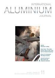
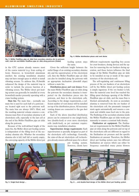
Fig. 3: Möller Fluidflow pipe air slide from secondary alumina silo to potroom<br />
wall; main bin and Möller Fluidflow pipe air slide along potroom (Dubal)<br />
in the GTC system already remove most<br />
of the coarse material (e. g. from scaling effects).<br />
However, in brownfield aluminium<br />
smelters the existing installation situation<br />
may not have enough space in which to install<br />
vibrating screens. To address this, FLSmidth<br />
enhanced the design of the material trap in<br />
order to include the process function of a<br />
vibrating screen. The Möller direct pot feeding<br />
system can generally be installed at every<br />
brownfield smelter presently operating with a<br />
crane feeding system.<br />
Main bin: The main bins <strong>–</strong> normally one<br />
main bin is used for each half of a potroom <strong>–</strong><br />
are located right next to the potroom wall.<br />
The main bins are always 100% filled, and<br />
the resulting material column ensures a continuous<br />
mass flow of secondary alumina to all<br />
electrolysis cells, e<strong>special</strong>ly to the last cell at<br />
the end of the Möller Fluidflow pipe air slide<br />
along the potroom.<br />
Because of the well-defined height of the<br />
main bin, the Möller direct pot feeding system<br />
is independent of the filling level of the secondary<br />
alumina silo. Whether the secondary<br />
alumina silo is full, half full or nearly empty,<br />
the conveying capacity of the Möller direct pot<br />
feeding system stays<br />
the same.<br />
Given the sufficient height between the<br />
outlet flange of an existing secondary alumina<br />
silo and the superstructure of the electrolysis<br />
cell, then the Möller Fluidflow pipe air slide<br />
can also be installed along the potroom with<br />
an appropriate declination (downhill slope)<br />
without a main bin.<br />
Distribution pieces and vent domes: From<br />
the main Möller Fluidflow pipe air slide along<br />
the potroom the secondary alumina is transported<br />
via the distribution pieces into the<br />
potroom, and then to the electrolysis cells.<br />
According to the design requirements, a sufficient<br />
number of vent domes will be installed<br />
on top of the distribution pieces. All necessary<br />
venting domes are connected to the gas duct<br />
of the GTC.<br />
Each of the above described distribution<br />
pieces can be connected to one (single-feed),<br />
two (double-feed) or even more electrolysis<br />
cells (multi-feed), as per customer requirements<br />
resp. installation situation.<br />
Superstructure design requirements: Each<br />
superstructure is <strong>special</strong>ly designed as part of<br />
the electrolysis cell’s technology. Generally,<br />
the state-of-the-art electrolysis cell technologies<br />
already ensure sufficient space for a direct<br />
pot feeding system.<br />
However, clients have<br />
Fig. 4: Möller distribution pieces and vent dome<br />
different requirements regarding free access<br />
for crust breakers, dosing devices and the option<br />
for removing the ore bunkers during operation,<br />
and these factors influence the final<br />
design of the Möller Fluidflow pipe air slide<br />
to be installed on top or inside of the superstructure<br />
of the electrolysis cell.<br />
The self-regulating and continuous filling<br />
process of the ore bunkers of an electrolysis<br />
cell by the Möller direct pot feeding system<br />
is simply ingenious. If the ore bunker is full,<br />
then the material cone level has reached the<br />
filling spout discharge opening of the Möller<br />
Fluidflow pipe air slide, and the mass flow is<br />
blocked automatically. As soon as secondary<br />
alumina is removed from the ore bunker of<br />
the electrolysis cell, the pneumatic transport<br />
starts again automatically and ensures a constant<br />
and reliable mass feed rate to the pots.<br />
The fluidising of the secondary alumina inside<br />
the Möller Fluidflow pipe air slide works permanently<br />
to ensure a constant bulk density.<br />
Fluidisation air equipment: The fluidisation<br />
air requirements for the Möller Fluidflow<br />
pipe air slide along the potroom and on top of<br />
the electrolysis cells are different in regard to<br />
the fluidisation air pressure and the specific<br />
fluidisation air amount. Therefore, the Möller<br />
direct pot feeding system uses two different<br />
fluidisation air sources which can either be<br />
frequency controlled rotary piston blowers<br />
Fig. 5: Single-feed design …<br />
Fig. 6: … and double-feed design of the Möller direct pot feeding system<br />
30 <strong><strong>ALU</strong>MINIUM</strong> · 1-2/2013