special - ALUMINIUM-Nachrichten – ALU-WEB.DE
special - ALUMINIUM-Nachrichten – ALU-WEB.DE
special - ALUMINIUM-Nachrichten – ALU-WEB.DE

Create successful ePaper yourself
Turn your PDF publications into a flip-book with our unique Google optimized e-Paper software.
<strong><strong>ALU</strong>MINIUM</strong> SMELTING INDUSTRY<br />
The specimens show the homogeneous welding<br />
attainable and how tight the two parts are pressed<br />
together. This improves the electric conductivity,<br />
and it transfers heat better then than other joints<br />
available on the market today.<br />
studs, the anode yoke and rod is directed to<br />
the automatic welding station. If the welding<br />
station is occupied, the anode yokes and rod<br />
wait at the intermediate storage zone. While<br />
one robot handles the new stud, checks and<br />
prepares it for a correct replacement and welding,<br />
the other two robots execute the welding<br />
operation simultaneously from both sides.<br />
Then the already repaired anode yoke and<br />
rod is returned into the system for rodding.<br />
Safety system: The whole of HMR’s ASRL<br />
is surrounded by a safety fence. Each robot<br />
station has an additional safety fence. If anyone<br />
opens a door in the fences, the system<br />
stops robot movements momentarily. A separate,<br />
moveable safety catch is placed around<br />
the chain centrifugal blast cleaning station.<br />
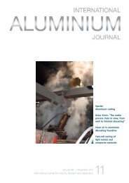
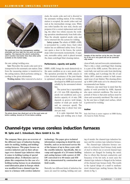
Samples of the stud bar cut by the saw. The quality<br />
of the cut is very good and can be systematically<br />
tested.<br />
the saw cutting / welding area.<br />
Saw: Thereafter the anode yoke and rod is<br />
transported to the automatic saw station. Data<br />
from the measuring station is transferred to<br />
the cutting station, which performs cutting according<br />
to the given information.<br />
Welding station: After removal of a stud or<br />
The photo shows two sliced part cut in the exact same cut<br />
before welding. Second cut 10 mm below welding.<br />
Performance, capacity and quality<br />
HMR’s ASRL brings the studs distinctively to<br />
the same condition as on a new anode yoke.<br />
The operation provided by ASRL ensures in<br />
a low electrical resistance of the joint thanks<br />
to optimised cutting and welding procedures<br />
developed by HMR and executed<br />
reliably by the automated robotic<br />
line.<br />
The system has a repeatability<br />
of < 0,1 mm (NB. depending on<br />
anode rod condition) and a productive<br />
capacity of ≤ 6 min. (NB.<br />
depends on groove weld design,<br />
number of studs per anode rod<br />
and on conveyor speed). The<br />
welding time is about four minutes<br />
per stud.<br />
It is quite important that the<br />
cutting and welding area is kept<br />
clean of bath, rust and iron scale contamination.<br />
That is why a chain centrifugal blast cleaning<br />
is a part of the ASRL system. This device prevents<br />
bath, rust and iron scale from interfering<br />
with welding, and it prolongs the life of saw<br />
blades (40% alumina content in bath causes<br />
rapid wear of saw blades). This cleaning allows<br />
up to 800-1,000 studs cut to be obtained from<br />
recommended saw blades.<br />
However, one must bear in mind that the<br />
quality of weld provided by ASRL depends<br />
also upon external conditions. The most important<br />
of these is that joint surfaces must be<br />
clean and accurately machined. The studs cut<br />
by the saw have a bright steel surface, which<br />
is preferred for welding.<br />
Author<br />
Italo Dal Porto is senior engineer at HMR Hydeq<br />
AS, based in Årdal, Norway.<br />
Channel-type versus coreless induction furnaces<br />
W. Spitz and C. Eckenbach, Marx GmbH & Co. KG<br />
The company Marx gives an overview of<br />
the different types of induction heating<br />
units for melting, holding and holding/<br />
casting furnaces. This paper focuses on<br />
coreless inductors and on their advantages<br />
over channel type inductors when<br />
it comes to holding /casting of <strong>special</strong><br />
aluminium alloys. It illustrates and explains<br />
this comparison for the case of a<br />
holding/casting furnace in an aluminium<br />
semi-fabrication plant in Europe which<br />
was modified from a channel-type furnace<br />
to a furnace with coreless inductor<br />
technology. The paper gives technical<br />
information comparing in detail the new<br />
benefits, such as an increased service life<br />
of the furnace of up to three years with<br />
the crucible inductor. Specifically, this revamp<br />
and upgrade of a 28 tonnes holding<br />
and casting furnace with a power of 200<br />
kW converted it to 40 tonnes and 450<br />
kW, as demonstrated by construction and<br />
field results.<br />
Basically two different kinds of induction furnaces<br />
are used for melting, holding and cast-<br />
ing of metals: the channel-type induction furnace<br />
and the coreless type induction furnace.<br />
The channel-type induction furnace consists<br />
of a refractory lined furnace body made<br />
of steel to which one or several channel-type<br />
inductors are flanged for heating the metal.<br />
Due to effects like thermal conductivity and<br />
buoyancy of the hot melt, in most cases the<br />
channel-type inductor is flanged at the bottom<br />
of the channel type furnace body. This results<br />
in the typical design of a small to mediumsized<br />
channel-type melting furnace like that<br />
shown in Fig. 1.<br />
46 <strong><strong>ALU</strong>MINIUM</strong> · 1-2/2013