AFRTS Defense Media Center Satellite Handbook
AFRTS Defense Media Center Satellite Handbook
AFRTS Defense Media Center Satellite Handbook
Create successful ePaper yourself
Turn your PDF publications into a flip-book with our unique Google optimized e-Paper software.
<strong>Defense</strong> <strong>Media</strong> <strong>Center</strong> <strong>Satellite</strong> <strong>Handbook</strong> V.3.26<br />
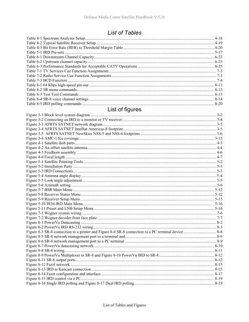
List of Tables<br />
Table 4-1 Spectrum Analyzer Setup.............................................................................................................................. 4-18<br />
Table 4-2 Typical <strong>Satellite</strong> Receiver Setup ................................................................................................................... 4-19<br />
Table 4-3 Bit Error Rate (BER) to Threshold Margin Table......................................................................................... 4-20<br />
Table 5-1 IRD Pre-sets .................................................................................................................................................. 5-17<br />
Table 6-1 Downstream Channel Capacity..................................................................................................................... 6-23<br />
Table 6-2 Upstream channel capacity............................................................................................................................ 6-23<br />
Table 6-3 Performance Standards for Acceptable CATV Operations........................................................................... 6-25<br />
Table 7-1 TV Services Cue Function Assignments......................................................................................................... 7-3<br />
Table 7-2 Radio Service Cue Function Assignments ...................................................................................................... 7-3<br />
Table 7-3 BCD Function ................................................................................................................................................. 7-4<br />
Table 8-1 64 Kbps high-speed pin-out .......................................................................................................................... 8-11<br />
Table 8-2 SR menu commands...................................................................................................................................... 8-13<br />
Table 8-3 Test Tool Commands .................................................................................................................................... 8-13<br />
Table 8-4 SR-8 voice channel settings .......................................................................................................................... 8-14<br />
Table 8-5 IRD polling commands ................................................................................................................................. 8-20<br />
List of figures<br />
Figure 3-1 Block level system diagram........................................................................................................................... 3-2<br />
Figure 3-2 Connecting an IRD to a monitor or TV receiver............................................................................................ 3-4<br />
Figure 3-3 <strong>AFRTS</strong> SATNET network diagram............................................................................................................... 3-5<br />
Figure 3-4 <strong>AFRTS</strong> SATNET IntelSat Americas-8 footprint........................................................................................... 3-5<br />
Figure 3-5 <strong>AFRTS</strong> SATNET NewSkies NSS-5 and NSS-6 footprints .......................................................................... 3-6<br />
Figure 3-6 AMC-1 Ku coverage.................................................................................................................................... 3-13<br />
Figure 4-1 <strong>Satellite</strong> dish parts.......................................................................................................................................... 4-3<br />
Figure 4-2 An offset satellite antenna.............................................................................................................................. 4-4<br />
Figure 4-3 Feedhorn assembly ........................................................................................................................................ 4-6<br />
Figure 4-4 Focal length ................................................................................................................................................... 4-7<br />
Figure 5-1 <strong>Satellite</strong> Pointing Tools.................................................................................................................................. 5-2<br />
Figure 5-2 Installation Parts ............................................................................................................................................ 5-3<br />
Figure 5-3 IRD Connections............................................................................................................................................ 5-3<br />
Figure 5-4 Antenna angle display.................................................................................................................................... 5-4<br />
Figure 5-5 Look angle adjustment................................................................................................................................... 5-5<br />
Figure 5-6 Azimuth setting.............................................................................................................................................. 5-6<br />
Figure 5-7 BSR Main Menu .......................................................................................................................................... 5-12<br />
Figure 5-8 Receiver Status Menu .................................................................................................................................. 5-12<br />
Figure 5-9 Receiver Setup Menu................................................................................................................................... 5-13<br />
Figure 5-10 9834 IRD Main Menu................................................................................................................................ 5-16<br />
Figure 5-11 Preset and LNB Setup Menu...................................................................................................................... 5-16<br />
Figure 7-1 Wegner system wiring ................................................................................................................................... 7-6<br />
Figure 7-2 Wegner decoder front face plate .................................................................................................................... 7-7<br />
Figure 8-1 PowerVu Datacasting .................................................................................................................................... 8-2<br />
Figure 8-2 PowerVu IRD RS-232 wiring........................................................................................................................ 8-3<br />
Figure 8-3 SR-8 connection to a printer and Figure 8-4 SR-8 connection to a PC terminal device ................................ 8-8<br />
Figure 8-5 SR-8 network management port to a terminal and......................................................................................... 8-9<br />
Figure 8-6 SR-8 network management port to a PC terminal ......................................................................................... 8-9<br />
Figure 8-7 PowerVu datacasting network ..................................................................................................................... 8-10<br />
Figure 8-8 SR-8 wiring.................................................................................................................................................. 8-11<br />
Figure 8-9 PowerVu Multiplexer to SR-8 and Figure 8-10 PowerVu IRD to SR-8......................................................8-12<br />
Figure 8-11 SR-8 output ports....................................................................................................................................... 8-12<br />
Figure 8-12 Fazzt network............................................................................................................................................. 8-15<br />
Figure 8-13 IRD to Kencast connection ........................................................................................................................ 8-15<br />
Figure 8-14 Fazzt configuration and interface............................................................................................................... 8-17<br />
Figure 8-15 IRD control via a PC.................................................................................................................................. 8-19<br />
Figure 8-16 Single IRD polling and Figure 8-17 Dual IRD polling.............................................................................. 8-19<br />
List of Tables and Figures


